
Catheter with occluding cuff

a catheter and occluding technology, applied in balloon catheters, medical science, surgery, etc., can solve the problems of no-flow condition and myocardial infarction, high incidence of distal embolic material release, and release of embolic material

Active Publication Date: 2007-01-23
EV3
View PDF56 Cites 121 Cited by
  • Summary
  • Abstract
  • Description
  • Claims
  • Application Information

AI Technical Summary

Benefits of technology

[0011]This invention is a device and a method that creates a seal to prevent the flow of blood during the treatment of vascular disease. A sealing cuff is disposed on a de

Problems solved by technology

Treatment of these degenerated grafts with PTCA or Stenting is associated with a high incidence of embolic material (vessel deposits) released distally.
This can result in a no-flow condition and myocardial infarction.
Similarly, treatment of carotid arteries and renal arteries by PTCA and Stenting can cause release of embolic material.
In the case of the carotid artery, emboli released can result in a stroke.
In the case of the renal artery, emboli release can result in the renal infarct and reduced renal function.
There is a risk of embolic material being released with any balloon expansion or passage of a treatment device through a diseased section of a vessel, with undesirable results to the patient.
A balloon occlusion approach can be problematic because no blood is flowing through the vessel during use of the treatment device and ischemia can develop quickly, particularly in saphenous vein grafts.
There is also no assurance that all trapped emboli are removed by suction.
A filter approach can be problematic because particles smaller than the filter pore size will pass through the filter and may cause embolic events or consequence, particularly in the brain.
There is also no assurance that trapped emboli will not be squeezed through the filter mesh during recovery.
Unfortunately, these approaches to embolic protection do not eliminate embolic events entirely because passage of the protection device or the catheter delivering the device across the diseased section of the vessel or lesion can dislodge embolic material prior to deployment of the device.
The disadvantages of this system are that a treatment balloon must be advanced into the vessel prior to creating stasis, and advancement of this balloon may liberate emboli.
Further, initial treatment with a balloon is not appropriate therapy for all procedures.

Method used


Image

  • Catheter with occluding cuff
  • Catheter with occluding cuff
  • Catheter with occluding cuff

Examples


Embodiment Construction

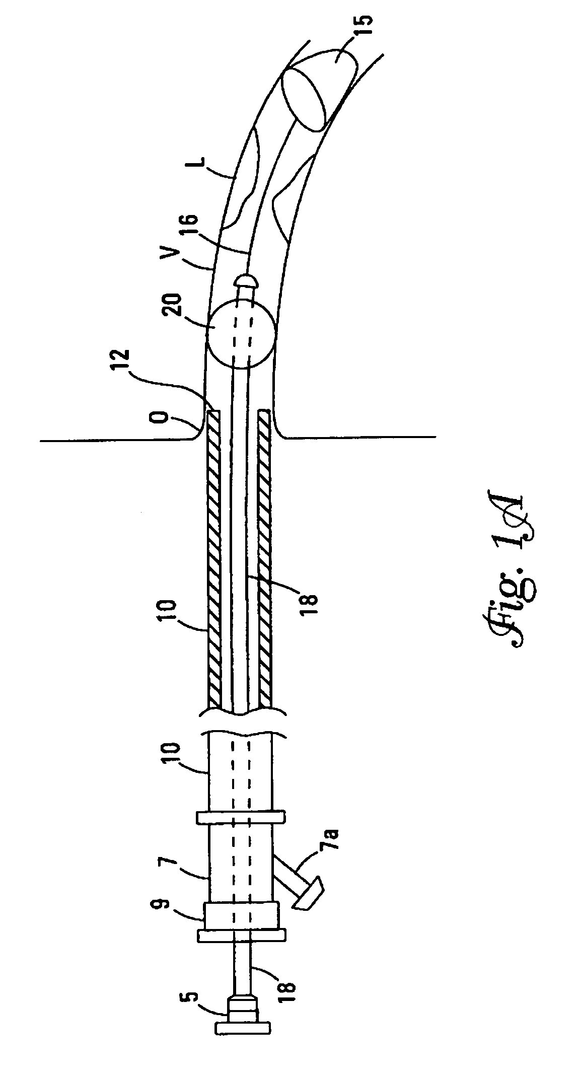
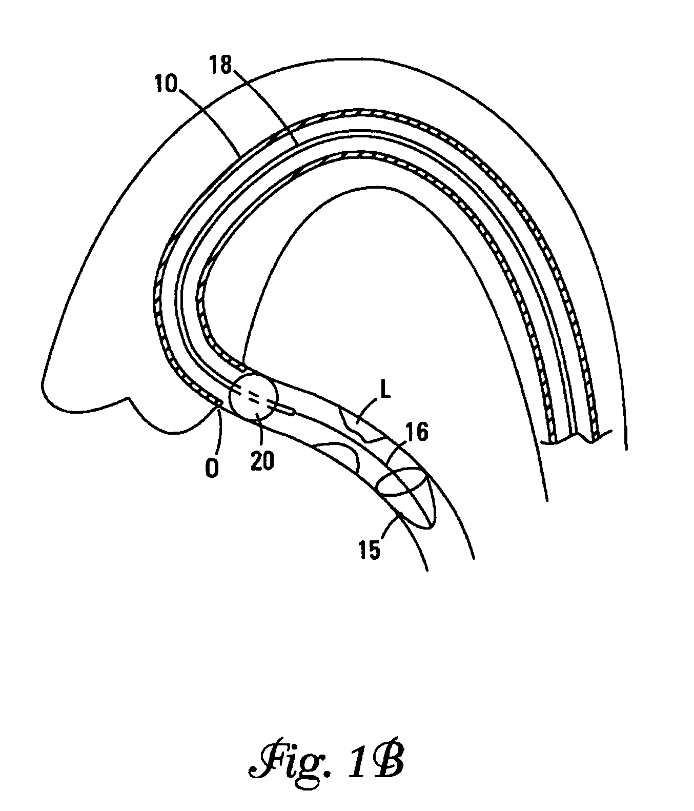
[0039]The terms “distal” and “proximal” as used herein refer to the relative position of the guidewires, control wires, catheters, and sealing cuff in a lumen. “Proximal” refers to a location upstream and “distal” refers to a location downstream. Flow of blood through a lumen normally moves from the proximal to the distal portions of the device of this invention, however, the device interrupts this flow.

[0040]The Figures describe various embodiments. Elements that vary from one embodiment to another but otherwise are similar in shape, size, relative placement, or function are denoted by suffices “a”, “b”, “c”, etc., and may be referred to in a general way by a number without its suffix.

[0041]The present invention is a device for occluding blood flow in a vessel at a location proximal to a treatment site in the vessel, thus preventing embolic material from moving distally in the vessel, prior to deployment of an embolic protection device positioned distally of the treatment site. A d...


PUM


Abstract

A device, method, and system of deploying an embolic protection device at a location distal to a treatment site in a vessel of a patient. A delivery catheter is encircled by a sealing member which is expandable from a delivery configuration to a deployed configuration. The device creates a seal to prevent the flow of blood during the treatment of vascular disease. A distal protection element is delivered by the delivery catheter and deployed to filter or remove embolic debris.

Description

FIELD OF THE INVENTION[0001]This invention relates to a device, a system, and a method for treating vascular disease. In particular, this invention relates to the occlusion of blood flow through a stenotic region and treatment of the region.BACKGROUND OF THE INVENTION[0002]Atherosclerosis or vascular disease is the leading cause of death in the world today. It is a disease of the arteries whereby deposits (plaque) build up over time in the walls of the arteries, restricting oxygenated blood flow to vital organs such as the heart, brain and other bodily tissue. A number of medical procedures have been developed to treat vascular disease such as Coronary Artery By-Pass Grafting (CABG) and Percutaneous Balloon Angioplasty (PTCA) and Stenting. These procedures are intended to restore normal flow through the arteries.[0003]In the case of CABG, the saphenous vein is harvested from the leg and used as a conduit to by-pass blood flow from the aorta to a point distal to an obstruction in a c...

Claims


Application Information

Patent Timeline
IPC IPC(8): A61M29/00A61M25/10A61F2/01A61F2/06A61F2/84
CPCA61F2/013A61B17/221A61F2/958A61F2230/0071A61F2230/008A61F2230/0067A61F2230/0006A61B2017/22067A61F2002/018
Inventor KUSLEIKA, RICHARD S.
Owner EV3
Learn More