Anchor assemblies in stretch-resistant vaso-occlusive coils

a vaso-occlusive coil and anchor assembly technology, applied in the field of stretch-resistant vaso-occlusive coils, can solve the problems of difficult inserting of twisted anchors into vaso-occlusive coils with smaller lumens, and its relatively large diameter

Inactive Publication Date: 2007-01-23
STRYKER EURO OPERATIONS HLDG LLC +1
View PDF32 Cites 104 Cited by
  • Summary
  • Abstract
  • Description
  • Claims
  • Application Information

AI Technical Summary

Benefits of technology

[0014]Although the present inventions should not necessarily be limited by this advantage, the presence of the link allows the stretch-resisting member to be located away from any heat generated at the proximal end of the primary coil during the manufacturing process. The flexible connection between the anchor coil and the link, provide the desired flexibility for the proximal end of the primary coil. By way of non-limiting example, the length of the anchor coil, having a preferable length of 1.0 mm, and link combination can be reduced to about 1.8 mm from 2.6 mm. The length of the link can be less than 1 mm.
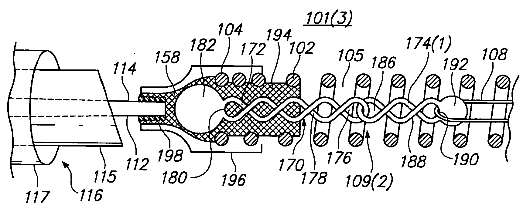
[0015]In accordance with a third aspect of the invention, the anchor assembly comprises an anchor chain comprising a proximal twisted link and a distal twisted or untwisted link, which is directly or indirectly coupled to the stretch-resisting member. The presence of the distal link allows the length of the proximal twisted link to be reduced, while locating the stretch-resisting member away from any heat generated at the proximal end of the primary coil during the manufacturing process. The reduction in the length of the relatively stiff proximal link, and the flexible connection between the proximal link and the distal link, provide the desired flexibility for the proximal end of the primary coil. By way of non-limiting example, the distal and proximal ends of the stretch-resisting member can be respectively affixed to the distal end of the primary coil and the distal link. By way of non-limiting example, a proximal twisted link having a preferable length of 2.6 mm can be reduced to about 1.2 mm, while the length of the distal link can be less than 1 mm. In the preferred embodiment, the anchor chain only includes the proximal and distal links, but can include additional links as well depending on the desired flexibility and length of the anchor chain. Filler material, such as, e.g., PET, polyamide, silicon, or polyurethane, can be used to provide structural integrity to the proximal end of the primary coil where the proximal link may be affixed within the primary coil lumen in the absence of an anchor coil. The anchor chain can be composed of any suitable biocompatible material, but in the preferred embodiment, platinum is used.
[0016]Although the present inventions should not necessarily be limited by this advantage, the presence of an anchor chain eliminates the need for a single piece proximal anchor, e.g., an anchor coil, or at the least, allows the length of the anchor coil to be reduced, while locating the stretch-resisting member away from any heat generated at the proximal end of the primary coil during the manufacturing process. The elimination or reduction in the length of the relatively stiff anchor coil, and the flexible connections formed by the anchor chain, provide the desired flexibility for the proximal end of the primary coil. By way of non-limiting example, a 2.6 mm single piece proximal anchor can be replaced with a 2.4 mm anchor chain, with each of the proximal and distal links being about 1.2 mm. The lengths of the respective proximal and distal links, however, need not be the same. For example, the distal link can be smaller than the proximal link.
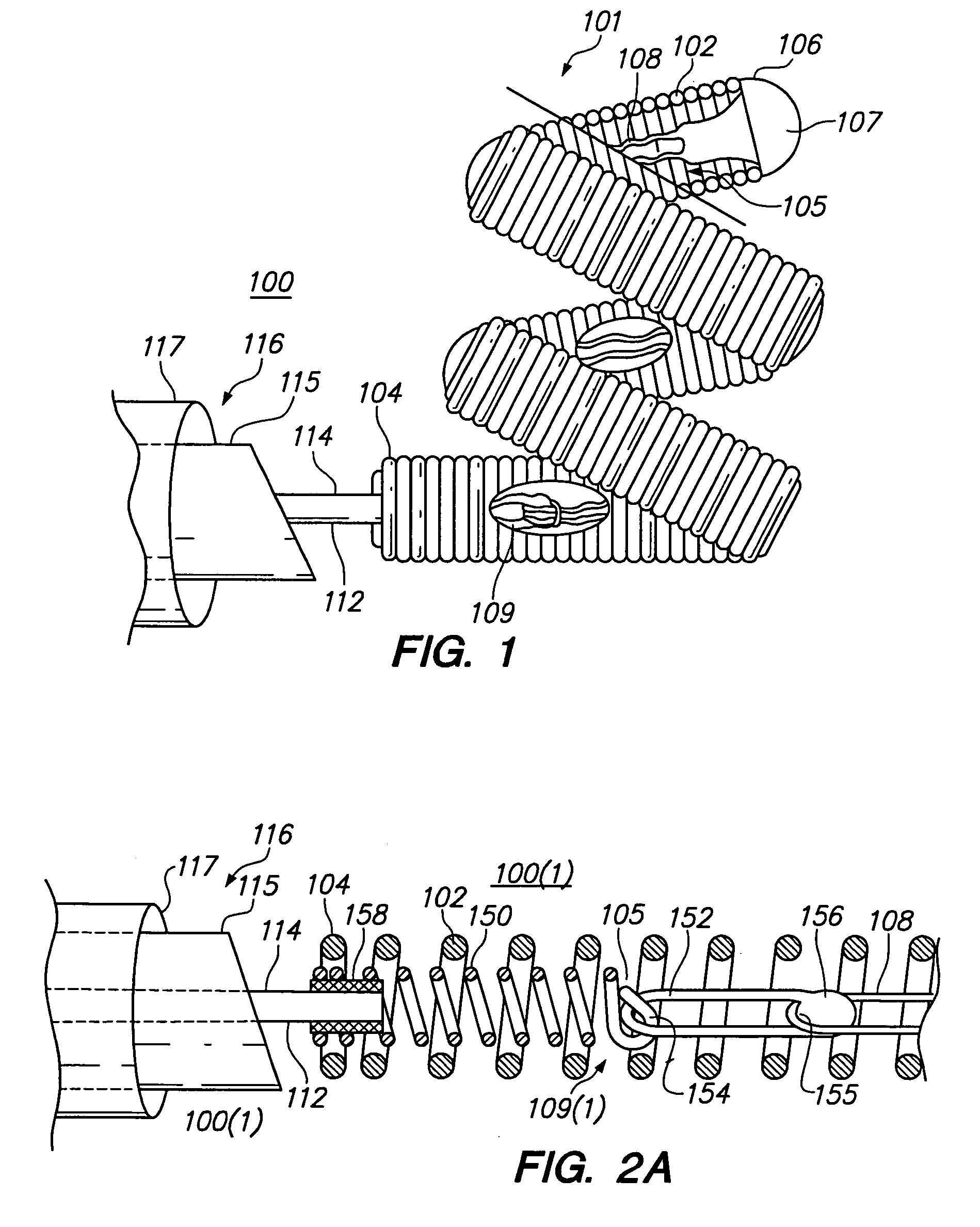
[0018]There are a variety of ways that the anchor coil and primary coil can be formed and incorporated into the vaso-occlusive device. For ease of assembly and to minimize the exertion of axial stress on the windings of the anchor and primary coils, the windings of the anchor and primary coils can be open-pitched. For example, a preferred method comprises making the outer primary coil by winding a first wire into a first helical coil so that the proximal end of the first helical coil has open-pitched windings, and making the anchor coil by winding a second wire into a second helical coil so that the second helical coil has open-pitched windings. The anchor coil is then incorporated into the primary coil, e.g., screwing, such that the open-pitched windings of the anchor coil are disposed between adjacent open-pitched windings of the primary coil.
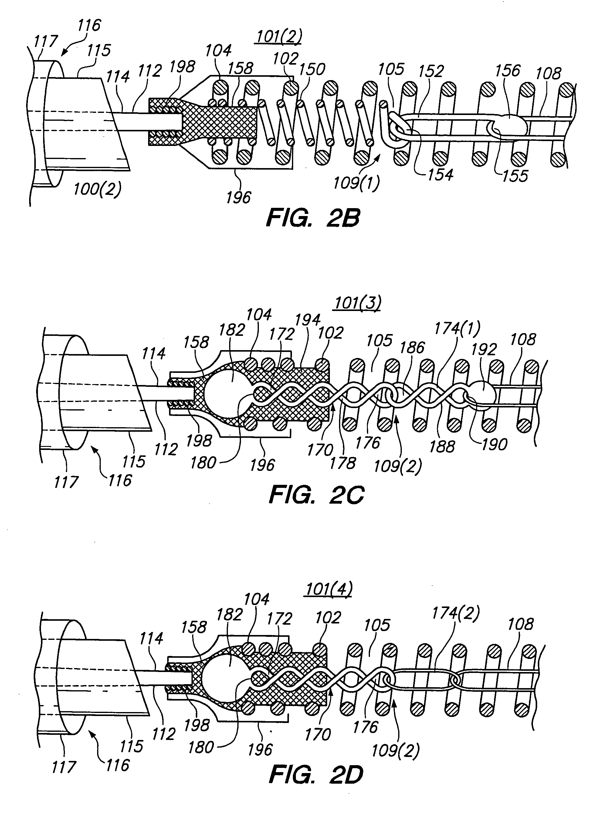
[0020]Although the present invention should not necessarily be limited by this advantage, the incorporation of the anchor coil into the primary coil decreases the wall thickness of the proximal end of the vaso-occlusive device, thereby providing the desired flexibility for the proximal end of the primary outer coil, while also locating the stretch-resisting member away from any heat generated at the proximal end of the anchor coil during the manufacturing process.
[0022]Although the present inventions should not necessarily be limited by this advantage, the presence of multiple detachment means allows for the deployment of vaso-occlusive devices with selectable length. This enables physicians to select the length of the deployed vaso-occlusive device as desired in light of the condition and size of the aneurysm being treated. The use of anchor assemblies to couple the stretch-resisting member to the primary outer coil segments allows the stretch-resisting member to be located away from any heat generated at the proximal end of the primary coil during the manufacturing process.

Problems solved by technology

This stiff section can cause problems during placement of the coil in the aneurysm by preventing the proximal end from curving into the interior of the aneurysm.
In addition, the twisted anchor, with its relatively large diameter, is difficult to insert into vaso-occlusive coils with smaller lumens.

Method used


Image

  • Anchor assemblies in stretch-resistant vaso-occlusive coils
  • Anchor assemblies in stretch-resistant vaso-occlusive coils
  • Anchor assemblies in stretch-resistant vaso-occlusive coils

Examples


Embodiment Construction

[0040]Referring to FIG. 1, a vaso-occlusive assembly 100 constructed in accordance with one preferred embodiment is illustrated. The vaso-occlusive assembly 100 includes a delivery device comprising a core wire 114 disposed within an elongate tubular catheter 117, and a vaso-occlusive device 101 detachably associated with the distal end of the delivery device 116 via use of detachable means 112 formed at the end of the core wire 114. In the illustrated embodiment, the detachable means 112 is an electrolytic severable joint, as will be described in further detail below. Other types of detachable means, such as mechanical, can be used to connect the vaso-occlusive assembly 100 to various other delivery devices. Thus, it can be appreciated that the vaso-occlusive device 101 can be associated with delivery devices other than those that use core wires.

[0041]The vaso-occlusive device 101 includes an outer primary coil 102, which has a proximal end 104, a distal end 106, and a lumen 105 ex...


PUM


Abstract

Vaso-occlusive devices are provided for occluding an aneurysm within the human vasculature. The vaso-occlusive device also includes a stretch-resisting member that extends through at least a portion of a lumen of the primary coil and is directly or indirectly attached to the primary coil at two locations axially separated from each other to prevent or minimize axial stretching of the primary coil. At one location, the stretch-resisting member is coupled to the primary coil via a flexible anchor assembly disposed within the lumen. In one embodiment, the anchor assembly may comprise an anchor coil and a link directly or indirectly coupled between the anchor coil and the stretch-resisting member. Alternatively, the anchor assembly may comprise a chain of twisted links.

Description

RELATED APPLICATIONS[0001]This application is related to application Ser. Nos. 10 / 185,671 and 10 / 185,669, which have been filed on the same date hereof, and are hereby fully and expressly incorporated herein by reference.FIELD OF THE INVENTION[0002]The field of the invention relates to implantable vaso-occlusive devices, and more particularly, to stretch-resistant vaso-occlusive coils.BACKGROUND OF THE INVENTION[0003]Vaso-occlusion devices are surgical implements or implants that are placed within the vasculature of the human body, typically via a catheter, to block the flow of blood through a vessel or an aneurysm stemming from the vessel via the formation of an embolus. One widely used vaso-occlusive device is a helical wire coil having windings that may be dimensioned to engage the walls of an aneurysm. Virtually all such vaso-occlusive implants are delivered by pushing the devices through wire-guided catheters.[0004]As an example of an early vaso-occlusive device, U.S. Pat. No. ...

Claims


Application Information

Patent Timeline
Patent Type & Authority Patents(United States)
IPC IPC(8): A61F2/00A61B17/12
CPCA61B17/12022A61B17/12113A61B17/12145A61B17/12154A61B2017/12095A61B2017/1205A61B2017/12063
Inventor AGANON, NESTORHUANG, ANNPIZARRO, MARIAMINCK, JR., JOHN L.
Owner STRYKER EURO OPERATIONS HLDG LLC
Why Eureka
Try Eureka