
Gas injection for glass melting furnace to reduce refractory degradation

a glass melting furnace and refractory technology, applied in the direction of combustion types, lighting and heating apparatus, combustion using lump and pulverulent fuel, etc., can solve the problems of reducing the structural integrity of the furnace, compromising the furnace crown structure, eroding, etc., and achieves the effect of reducing alkali vapor corrosion

Inactive Publication Date: 2007-01-30
BOC GRP INC
View PDF38 Cites 25 Cited by
  • Summary
  • Abstract
  • Description
  • Claims
  • Application Information

AI Technical Summary

Benefits of technology

[0008]The present invention relates to glass melting furnaces constructed or modified, and operated to reduce the detrimental effects of alkali vapor from sodium (Na), potassium (K) and lithium (Li), such as sodium hydroxide (NaOH), upon furnace refractories in a region of the furnace, such as the melting zone.
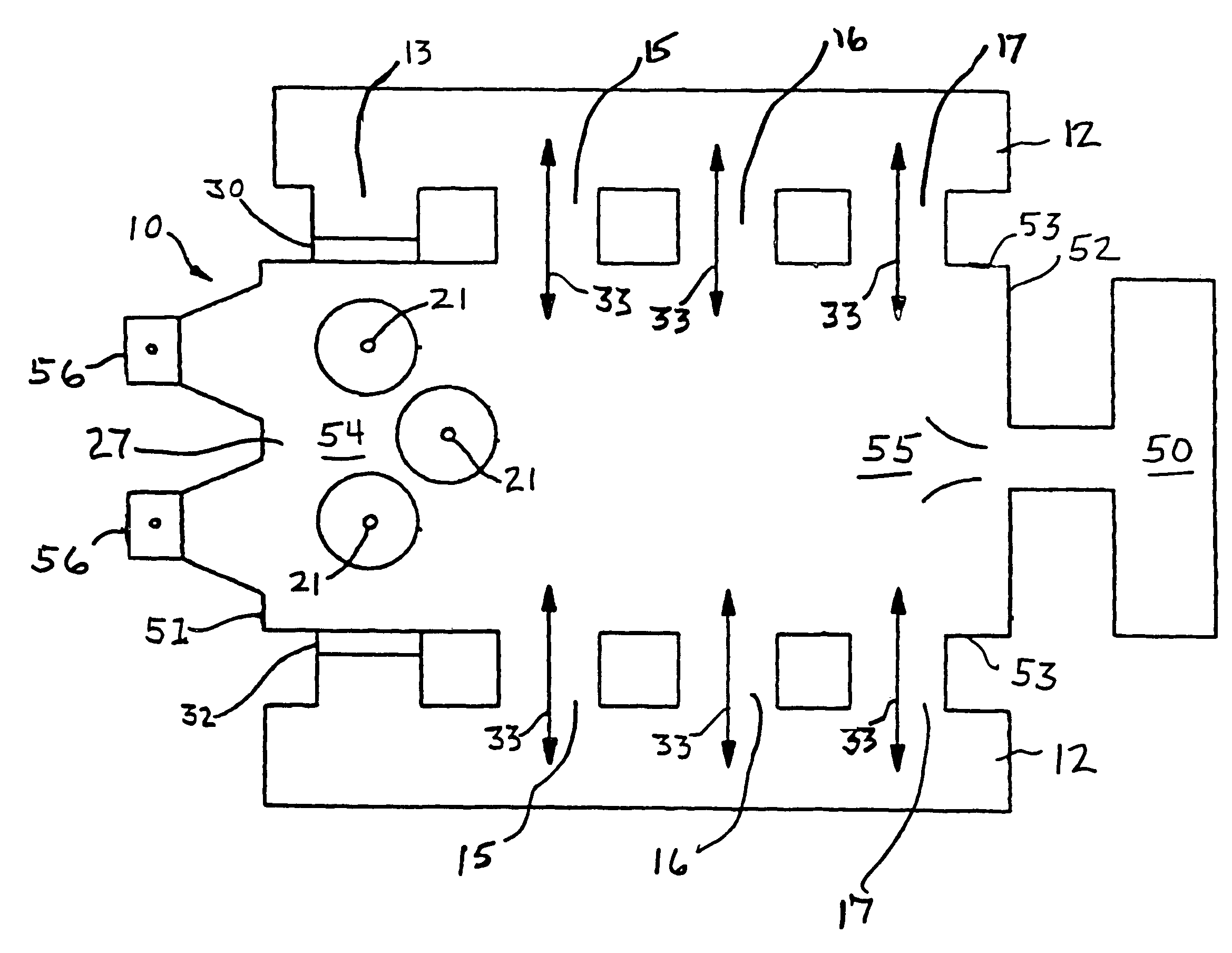
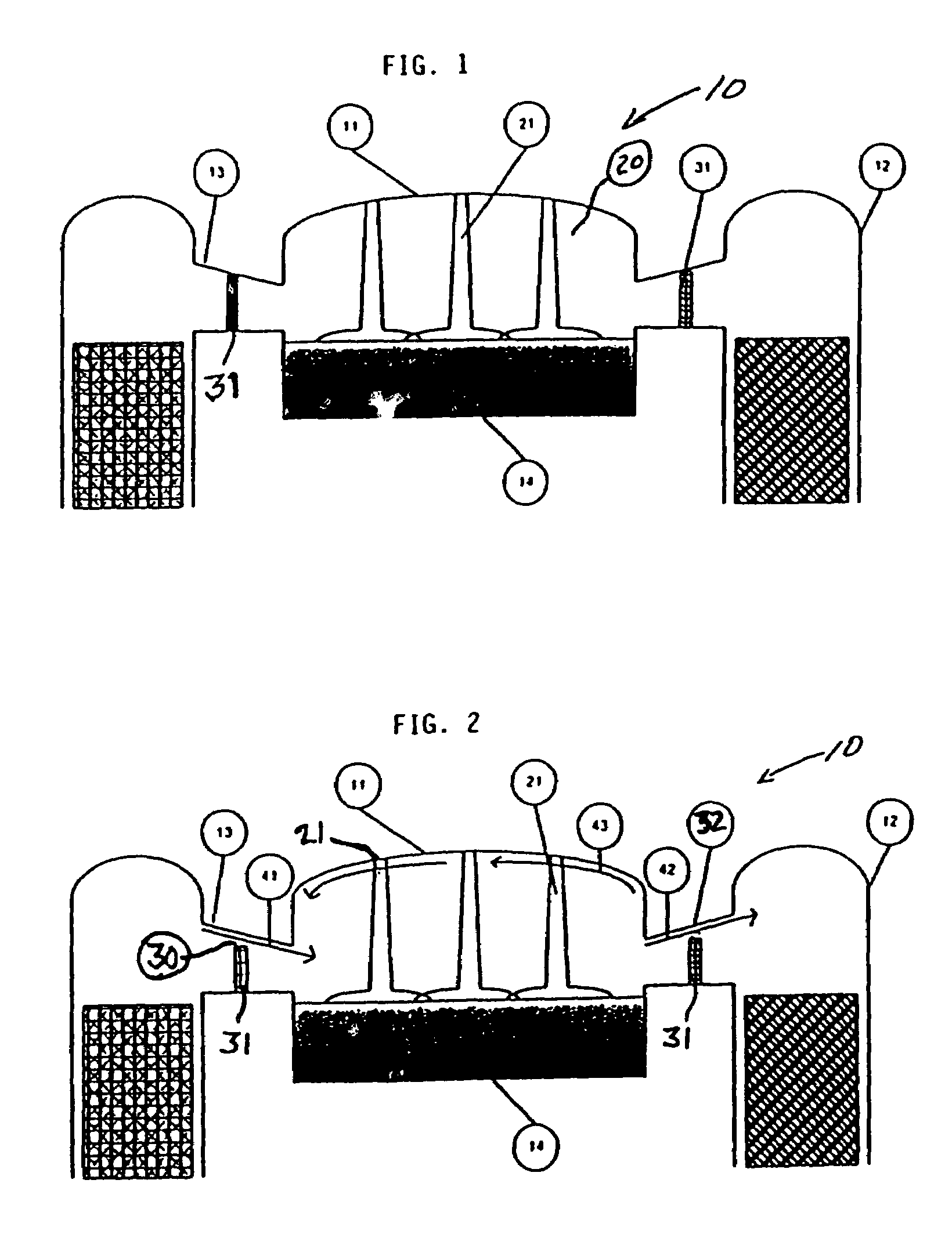
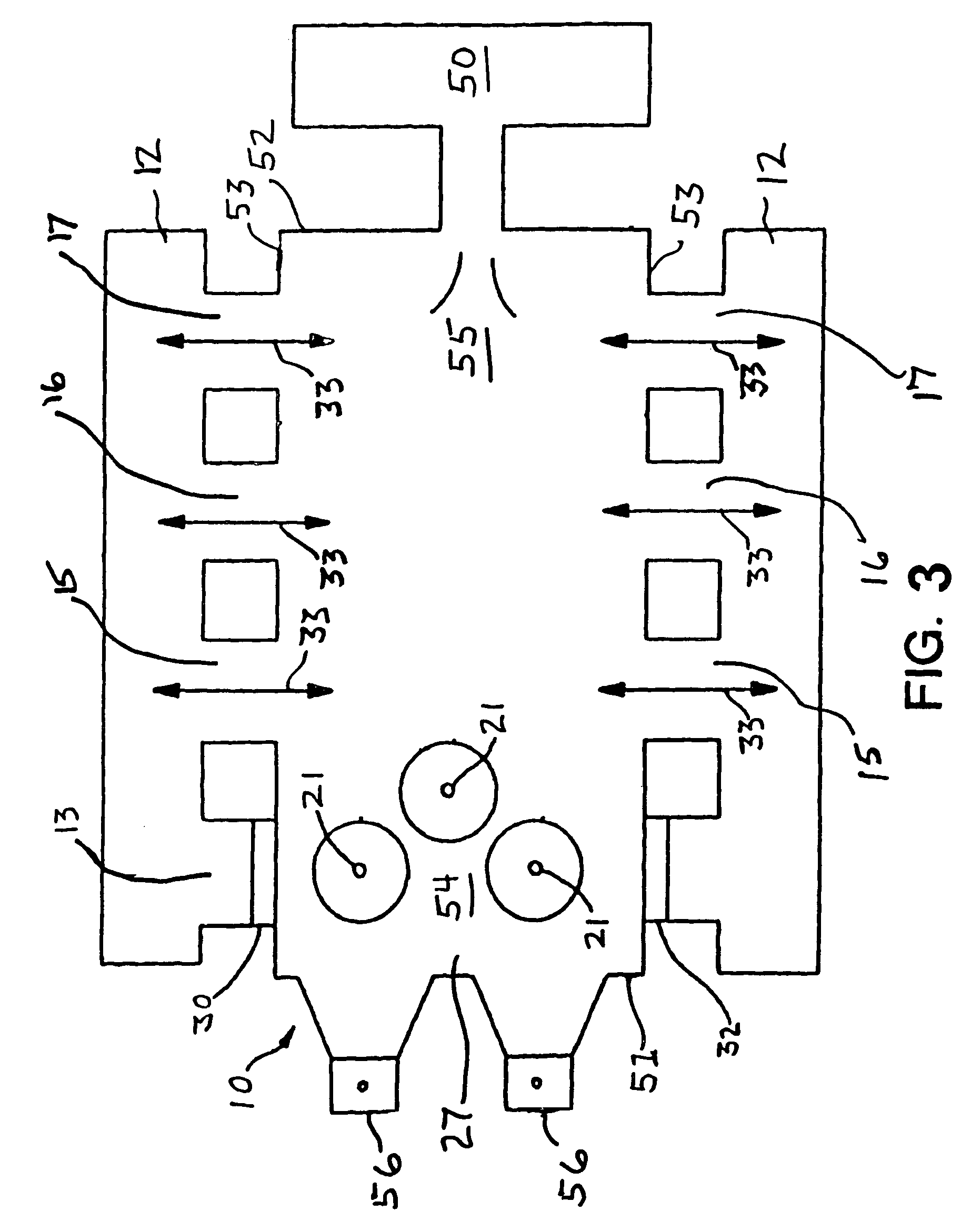
[0009]In one embodiment, the present invention provides a gas injection system and method for a glass melting furnace to reduce corrosion of silica refractories by evacuating alkali vapors, such as NaOH, or substantially reducing the residence time of any alkali at the refractory superstructure.
[0013]The present invention provides distinct advantages over known furnaces having the high alkali concentration environment and the disadvantages associated therewith by i) substantially reducing or diluting the concentration of the alkali vapor, such as NaOH, in the furnace, ii) providing movement and displacement of gases in the furnace thus reducing residence time of the alkali vapor in the oxy-fuel zone and the associated stagnation and deleterious effects associated with the corrosive aspects of alkali hydroxides, such as NaOH, and iii) providing a glass melt furnace construction that promotes the homogenization of the high alkali vapor concentration oxy-fuel region gases with lower alkali vapor concentration gases, optionally from a non-oxy-fuel or air-fuel region or zone.
[0016]The present invention also provides a method for reducing alkali vapor corrosion of furnace refractory structures in a glass melting furnace having an upstream melting zone and a downstream fining zone; a charging section in the melting zone; and at least one oxy-fuel fired burner disposed in the melting zone proximate the charging section to provide an oxy-fuel combustion region; comprising: providing at least one gas inlet proximate to the oxy-fuel combustion region; introducing a first volume of gas, having no or a dilute partial pressure of alkali vapor, from the at least one gas inlet into the oxy-fuel combustion region; at least partially displacing a second volume of gas, optionally substantially equal to the first volume, from the oxy-fuel combustion region, the second volume having a partial pressure of alkali vapor higher than the first volume; and, providing at least one gas outlet adapted to provide an exit for a volume of furnace atmosphere.
[0017]The present invention also provides a method for reducing alkali vapor corrosion of furnace refractory structures in a glass melting furnace having walls supporting a crown substantially enclosing an upstream melting zone and a downstream fining zone; a charging section in the melting zone; and at least one oxy-fuel fired burner disposed at the crown above the melting zone proximate the charging section to provide an oxy-fuel combustion region; comprising providing at least one gas inlet proximate to the oxy-fuel combustion region; introducing a first volume of gas, having no or a dilute partial pressure of alkali vapor, into the oxy-fuel combustion region; at least partially displacing a second volume of gas proximate the crown in the oxy-fuel combustion region, the second volume having a partial pressure of alkali vapor higher than the first volume; and, providing at least one gas outlet adapted to provide an exit for a volume of furnace atmosphere, optionally substantially equal to the first volume.

Problems solved by technology

These alkali hydroxides vaporize out from the molten glass, and can react with the furnace refractory.
The alkali hydroxides such as NaOH can corrode the refractory superstructure, particularly where the residence time of the NaOH is unusually long, such that the effects of the NaOH and the partial pressure associated therewith in the closed furnace can compromise the structural integrity of the furnace by corrosion and subsequent melting of the crown of the furnace.
As the residence time of the NaOH increases, and concurrently the concentration of the alkali increases, the liquid phase will continue to dissolve more of the silica bricks in the furnace refractory superstructure, and will ultimately erode and compromise the furnace crown structure.

Method used


Image

  • Gas injection for glass melting furnace to reduce refractory degradation
  • Gas injection for glass melting furnace to reduce refractory degradation
  • Gas injection for glass melting furnace to reduce refractory degradation

Examples


example 1

Retrofit with Roof Mounted Oxy-Fuel Burners

[0052]One demonstration of this invention was the oxygen boosting, 100% oxygen conversion, re-conversion to oxygen boost and finally conventional air fuel firing of an existing hot three-port cross-fired regenerative furnace. The furnace was initially firing all air fuel. Port One firing was replaced with at least one roof mounted oxygen fuel burner. The furnace fired conventionally air fuel regenerative on the remaining two ports. In the second phase, Port Two firing was then replaced with at least one roof mounted oxy-fuel burner and the furnace fired conventionally air fuel regenerative on the third port. In the third phase, Port Three firing was replaced with energy in the already installed roof-mounted oxy-fuel burners. The furnace capacity was increased from 55 to 85 tons per day with reduced energy input from 23.5 mm BTU / hr to 18 mm BTU / hr. The furnace was re-converted to air fuel firing in incremental stages. This example demonstrat...

example 2

Burner and Burner Block with Integral Oxygen Staging

[0053]An oxy-fuel burner provided with integral staging of oxygen, by means of the burner configuration or the burner in combination with the burner block, has been shown to provide increased heat transfer and reduced NOx. According to the present invention, at least one of this type of integrally staged burner is provided in the roof of a glass melting furnace. The burner is ideally positioned over the raw batch materials and is preferably angled such that the angle alpha (∝ being the angle of the axis of the burner in the direction of firing to the horizontal plane of the furnace or melt) equals about 91° to about 135° in the direction of the glass flow in the furnace.

example 3

A Burner and Burner Block with External Oxygen Staging

[0054]It has been shown that a burner with burner block mounted in the roof of a glass melting furnace with 2–8 oxygen injectors external to the burner and block can produce higher heat transfer than a non-staged burner. The burner is preferably angled from about 91° to about 135° relative to the surface of the glass and in the direction of the glass flow in the furnace. According to this example, 0% to about 90% of the stoichiometric combustion oxygen is injected through the primary oxygen burner, and the remaining 100% to about 10% secondary combustion oxygen is injected through the oxygen injectors, which are angled from about 0° to about 90° relative to the surface of the glass. As it can be appreciated by one skilled in the art, the number, angle and amount of staging ports is designed specifically for each furnace, in order to delay the combustion of the fuel until it impinges on or near the surface of the raw glass batch m...


PUM

PropertyMeasurementUnit
Flow rateaaaaaaaaaa

Abstract

A glass melting furnace has a gas inlet positioned proximate to a charging section oxy-fuel combustion region to introduce gas into the region and to at least partially displace gas having a partial pressure of alkali vapor from the region, and optionally a gas outlet is adapted to provide an exit for a volume of furnace atmosphere. A method for reducing alkali vapor corrosion of glass furnace refractory structures includes providing a gas inlet proximate to the oxy-fuel combustion region; introducing a volume of gas from the inlet into the region, displacing a volume of gas having a partial pressure of alkali vapor from the region; and, optionally providing a gas outlet adapted to provide an exit for a volume of furnace atmosphere.

Description

CROSS-REFERENCE TO RELATED APPLICATIONS[0001]The present application claims priority under 35 U.S.C. §119(e) from U.S. Provisional Patent Application No. 60 / 309,528, filed on Aug. 2, 2001, and is a continuation in part of U.S. Ser. No. 09 / 798,826, filed on Mar. 2, 2001, now U.S. Pat. No. 6,705,117, which is a continuation in part of U.S. Ser. No. 09 / 374,921, filed Aug. 16, 1999, now U.S. Pat. No. 6,422,041.BACKGROUND OF THE INVENTION[0002]Glass melting furnaces include a refractory surface or superstructure with an interior surface of the superstructure exposed to the harsh heated chemical environment of the furnace. A portion of the superstructure or roof, referred to in the industry as the crown of the furnace, is generally constructed from silica refractory bricks or silica bricks, which are referred to herein also as “bricks.” Oxy-fuel burners, used to melt glass-forming materials in alkali-based glass melting furnaces, generate high concentrations of alkali hydroxide vapor in t...

Claims


Application Information

Patent Timeline
IPC IPC(8): C03B5/167C03B5/237C03B5/235F23C5/00F23C6/04F23D14/02F23D14/32F23D17/00F23L7/00
CPCC03B5/193C03B5/2353C03B5/425F23C6/047F23D14/02F23D14/32F23D17/002F23L7/00F23C5/00C03B2211/30C03B2211/40C03B2211/60Y02E20/344F23L2900/07005Y02P40/57Y02E20/34Y02P40/50
Inventor SIMPSON, NEIL GEORGELEBLANC, JOHN R.PRUSIA, GREGORY FLOYD
Owner BOC GRP INC
Learn More