Distal protection double balloon catheter

a double-ballon catheter and distal protection technology, applied in balloon catheters, medical science, surgery, etc., can solve problems such as damage to organs and tissues, and achieve the effect of maintaining tissue viability

Inactive Publication Date: 2007-01-30
DON MICHAEL INT
View PDF16 Cites 5 Cited by
  • Summary
  • Abstract
  • Description
  • Claims
  • Application Information

AI Technical Summary

Benefits of technology

[0004]The invention provides a novel system that allows an angioplasty treatment, possibly with stenting or primary stenting, to be performed, while preventing the entry of debris resulting from such treatment into the distal microcirculatory system of a patient and assuring a continued supply of blood flow downstream of the obstruction during the angioplasty treatment and protection of organs and tissue downstream of the treatment site against damage that might be caused by debris resulting from the treatment.
[0006]The annular bypass lumen is formed adjacent the outer wall of the catheter. Therefore, the blood inlet and outlet openings in communication with the bypass flow lumen can be formed in a simple manner. In addition, these openings can be made relative large to assure an adequate blood flow, a flow of at least 30 cc / min being considered necessary to maintain tissue viability.

Problems solved by technology

Treatments of this type typically produce debris that, if allowed to enter the microcirculatory system downstream of the treatment site, can cause damage to organs and tissues.

Method used


Image

  • Distal protection double balloon catheter
  • Distal protection double balloon catheter
  • Distal protection double balloon catheter

Examples


second embodiment

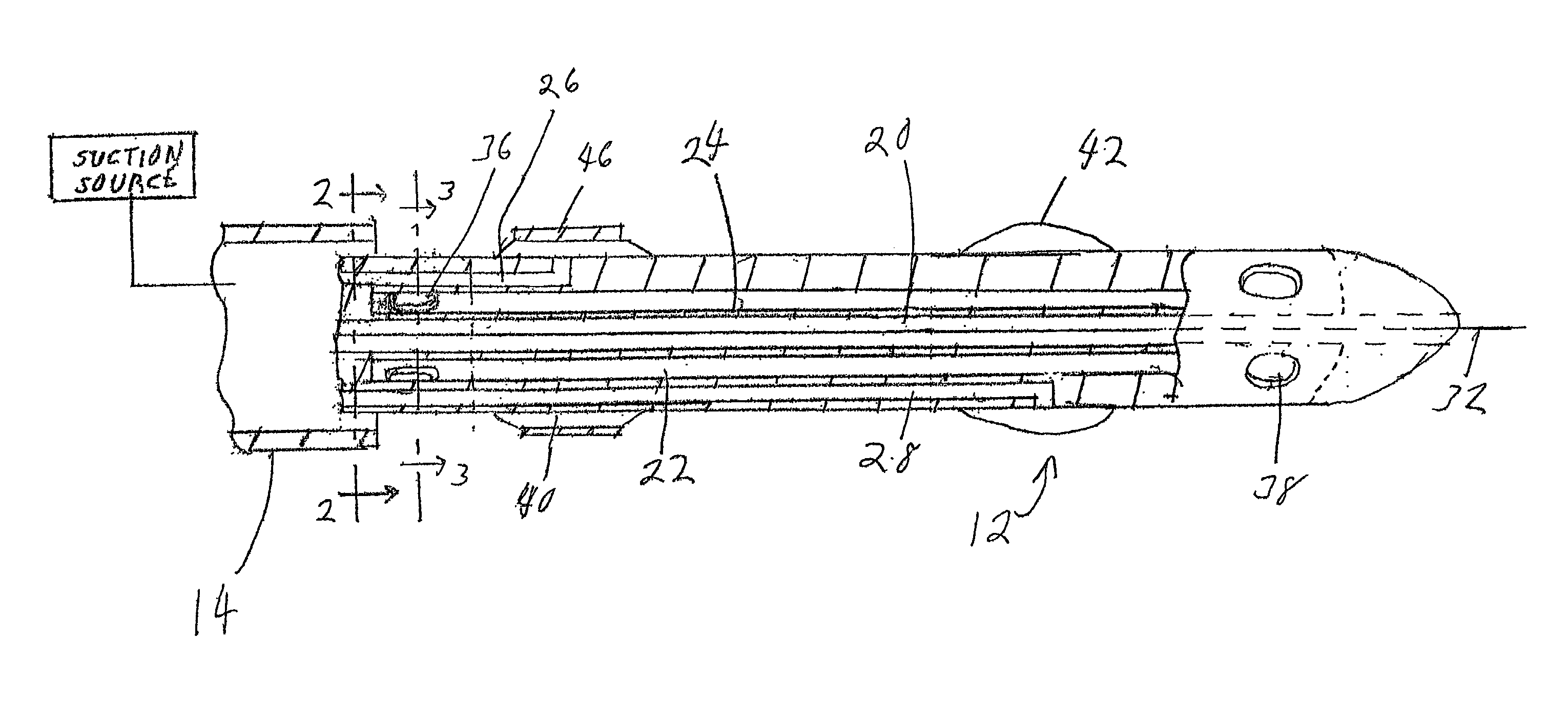
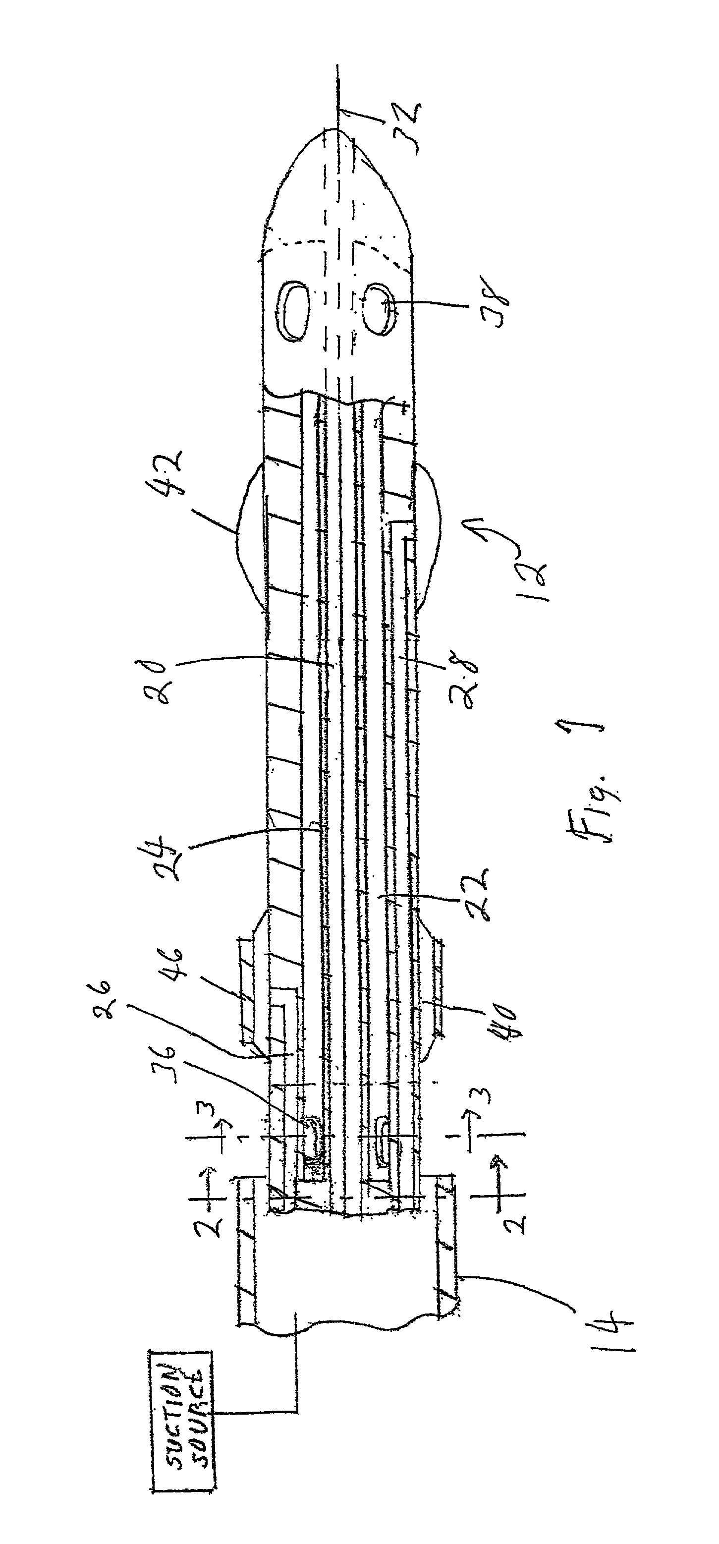
[0025]the a system according to the invention is shown in FIGS. 4–37 and is composed essentially of a dilatation and embolic blocking catheter 112 and a surrounding, movable suction catheter 114, which may be in the form of a hypo tube.

[0026]According to this embodiment, catheter 112 is a thin-walled body that is hollow, except for balloon inflation lumens, to be described below, to provide a blood bypass flow lumen 122 having a maximum cross section. Catheter 112 is provided with a proximal balloon inflation lumen 126 and a distal balloon inflation 128. Lumens 126 and 128 are the only structures within catheter 112 and thus the only structures that reduce the cross section of lumen 122. Lumen 122 can, but need not, extend the full length of catheter 112 and has a small diameter opening at the distal end thereof for passage of a guidewire 132 that serves to guide catheter 112 to a desired treatment site. Preferably, the opening is made only slightly larger in diameter than guidewire...

third embodiment

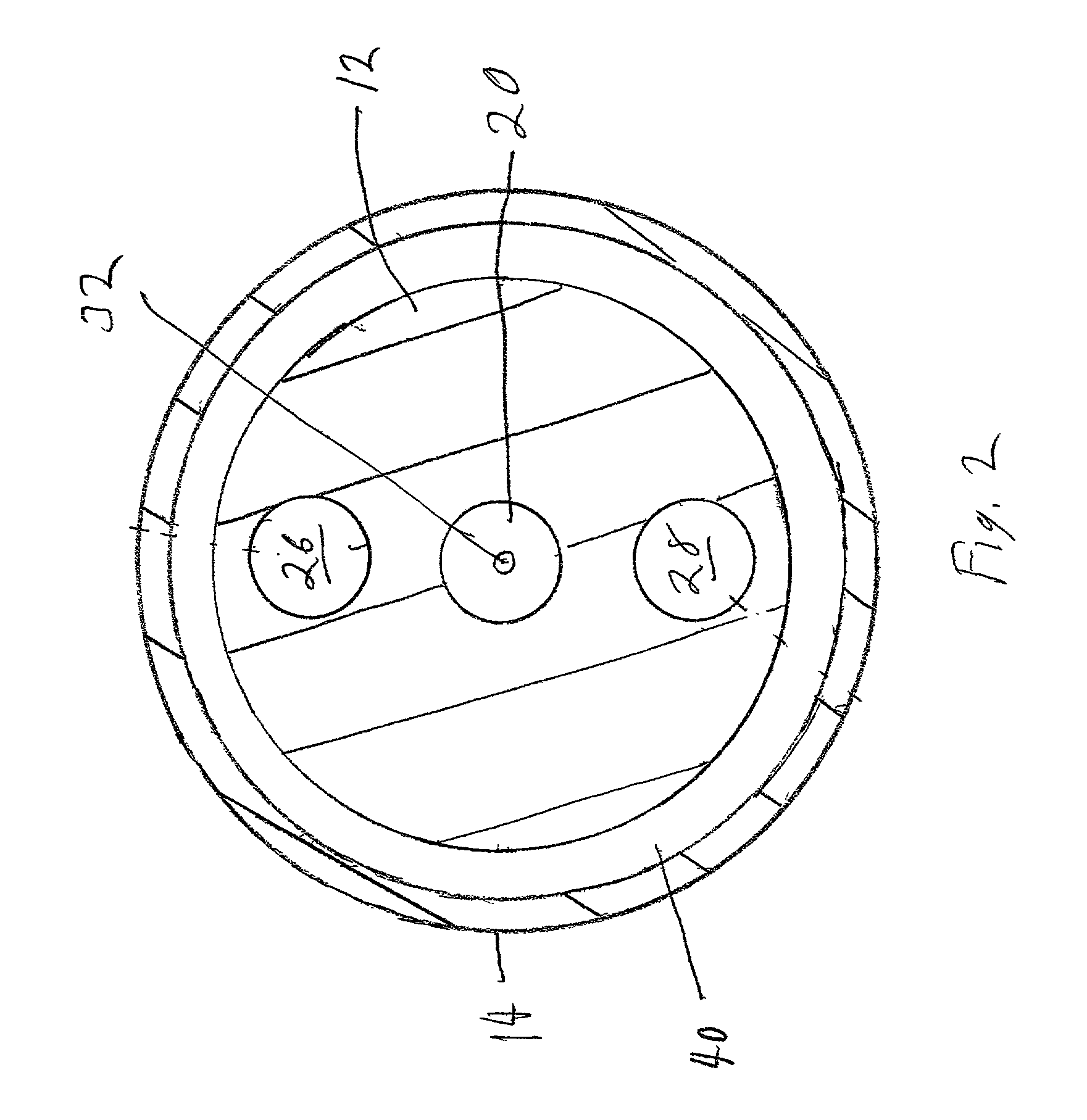
[0036]the invention is illustrated in FIG. 8. This embodiment differs from those previously described in two basic respects: balloons 140 and 142 are mounted directly adjacent to one another; and the outer diameter of catheter 212 changes along the length of the catheter, having a larger value, d1, at least in the region aligned with balloon 140 and a smaller diameter, d2, over all or a part of its length between balloon 140 and the distal end of the catheter. This configuration will act as a sump that increase blood flow through lumen 122. In addition, as described above with respect the embodiment of FIGS. 4–7, the wall thickness of catheter 212 in the region between balloon 140 and the distal end can be smaller than in the region aligned with balloon 140. In practical embodiments of the catheter of FIG. 8, d1 can have a value between 3 and 5 Fr and d2 can have a value between 2 and 4 Fr, with d1 always being greater than d2.

[0037]By placing balloon 142 directly adjacent balloon 1...


PUM


Abstract

A system for performing a medical treatment in a blood vessel while providing downstream microcirculatory system protection, the system being composed of: a catheter having a longitudinal axis, a distal end, an outer lateral surface, a central blood bypass flow lumen extending along the longitudinal axis and opening at the distal end, blood flow inlet and outlet openings extending from the lateral surface and communicating with the bypass flow lumen, and first and second inflation lumens extending to the lateral surface at respective first and second locations that are spaced apart along the longitudinal axis and that are between the inlet openings and the outlet openings; and first and second inflatable members secured to the lateral surface and each having an interior that communicates with a respective one of the first and second inflation lumens, wherein the catheter has a thin outer wall enclosing a hollow interior that is completely occupied by the bypass flow lumen, except for the space occupied by the first and second inflation lumens.

Description

[0001]This is a continuation-in-part of U.S. application Ser. No. 10 / 005,699, filed on Dec. 7, 2001BACKGROUND OF THE INVENTION[0002]The present invention relates to the treatment of obstructions in body passages, and particularly in arteries.[0003]Treatments of this type typically produce debris that, if allowed to enter the microcirculatory system downstream of the treatment site, can cause damage to organs and tissues.BRIEF SUMMARY OF THE INVENTION[0004]The invention provides a novel system that allows an angioplasty treatment, possibly with stenting or primary stenting, to be performed, while preventing the entry of debris resulting from such treatment into the distal microcirculatory system of a patient and assuring a continued supply of blood flow downstream of the obstruction during the angioplasty treatment and protection of organs and tissue downstream of the treatment site against damage that might be caused by debris resulting from the treatment.[0005]The system according ...

Claims


Application Information

Patent Timeline
Patent Type & Authority Patents(United States)
IPC IPC(8): A61F2/06A61F2/01A61F2/84A61M25/00A61M29/02
CPCA61F2/013A61F2/958A61M25/104A61M25/0023A61M2025/1097A61M2025/0004A61M2025/0079A61M2025/1052
Inventor DON MICHAEL, T. ANTHONY
Owner DON MICHAEL INT
Why Eureka
Try Eureka