Fractionating apparatus

a technology of teflon and teflon, which is applied in the direction of feed/discharge, chemical/physical processes, particle separator tubes, etc., can solve the problems of poor hydrophobic properties of the probe material, poor hydrophobic properties of the silica or peek used as the probe material, and the surface of the probe coated with teflon that cannot withstand long-term service, etc., and achieves the effect of cheap production

Active Publication Date: 2007-01-30
SHIMADZU CORP
View PDF19 Cites 1 Cited by
  • Summary
  • Abstract
  • Description
  • Claims
  • Application Information

AI Technical Summary

Benefits of technology

[0008]Thus, it is an object of the invention to provide a fractionating apparatus that can uniformly drip the sample liquid droplet on the sample plate stably for a long time.
[0014]Also, the tube made of the hydrophobic material requires no special coating technique, because the tube itself is made of the hydrophobic material but is not coated with the hydrophobic material, whereby the fractionating apparatus is produced cheaply.

Problems solved by technology

However, since stainless, fused silica or PEEK used as the material of the probe has poor hydrophobic property, when a liquid having great surface tension such as water is flowed, a liquid droplet may rise up the outside surface of the probe, depending on the surface tension of the sample liquid to be dripped.
However, a special coating technique is needed to coat Teflon on the surface of the probe, and the surface of the probe coated with Teflon does not withstand the service for a long time due to a life of coating.

Method used


Image

  • Fractionating apparatus
  • Fractionating apparatus
  • Fractionating apparatus

Examples


Embodiment Construction

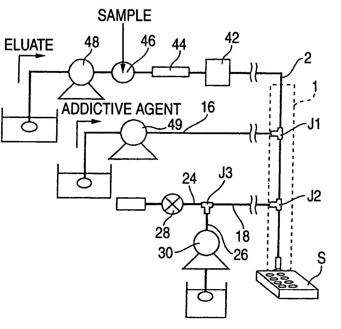
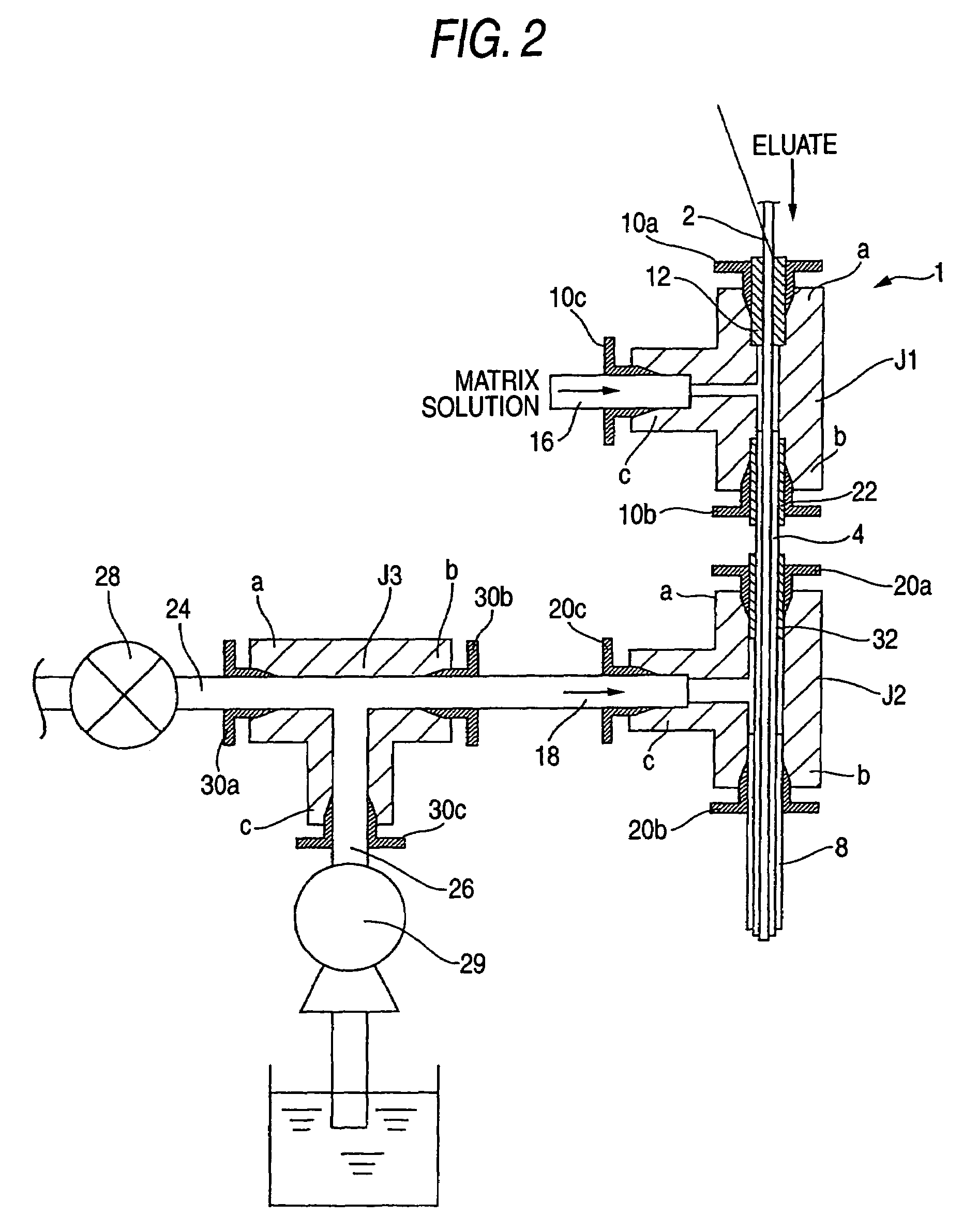
[0017]FIG. 1 is a schematic view showing a liquid chromatograph with a fractionating apparatus according to one embodiment of the invention.

[0018]The high performance liquid chromatograph comprises a pump 48 for feeding eluate, an injector 46 for injecting a sample, a column 44 for separating the sample constituents, and a detector 42, which are disposed along the flow passage of eluate. A probe 1 for dripping the liquid droplet is connected via a capillary 2 downstream of the detector 42.

[0019]The probe 1 comprises the T-type three-way joints J1 and J2, in which an upstream joint J1 connects the capillary 2 for feeding the eluate and a tube 16 for feeding a matrix solution, and a downstream joint J2 connects the capillary 2 and a tube 18 for supplying the air and acetone as rinsing solution, in which a tip portion on the exit side of the probe 1 forms a triple tube structure.

[0020]The eluate is fed by the pump 48, and a sample is injected from the injector 46. The sample injected f...


PUM

PropertyMeasurementUnit
contact angleaaaaaaaaaa
hydrophobicaaaaaaaaaa

Abstract

A tip portion of a probe has a triple tube structure in which a fused silica capillary on the innermost side, a capillary made of FEP outside the fused silica capillary, and a stainless pipe on the outermost side are disposed coaxially. An eluate from a liquid chromatograph flows through the innermost flow passage, a matrix solution flows through the flow passage between the fused silica capillary and the FEP capillary, and a rinsing solution or air flows through the flow passage between the FEP capillary and the pipe.

Description

BACKGROUND OF THE INVENTION[0001]1. Field of the Invention[0002]The present invention relates to a fractionating apparatus having a probe for dripping a sample liquid fed from a liquid feed mechanism such as an HPLC (High Performance Liquid Chromatograph), or the sample liquid with an additive agent, as a liquid droplet from a tip portion of the probe onto a plate such as a microplate or sample plate, and preparing a sample to be analyzed with MALDI-TOF-MS (Matrix Assisted Laser Desorption Ionization Time-Of-Flight Mass Spectrometry) or FT-IR (Fourier Transform Infrared Spectrophotometer).[0003]2. Description of the Related Art[0004]In the related art, when a sample liquid such as eluate from the liquid chromatograph is fractionated and captured on a sample plate for an analyzer of MALDI-TOF-MS or the like, for example, the sample liquid is automatically dripped and fractionated from the probe onto the sample plate. Usually, the fractionating apparatus has an X-Y stage and a Z stage...

Claims


Application Information

Patent Timeline
Patent Type & Authority Patents(United States)
IPC IPC(8): B01D15/08B01L3/02G01N27/62G01N1/18G01N27/64G01N30/80G01N30/84G01N35/10
CPCB01L3/0241G01N30/84B01L2300/0838B01L2300/0867G01N2030/8441B01L2400/0487G01N2030/8417B01L2400/02
Inventor IWATA, YOSUKE
Owner SHIMADZU CORP
Why Eureka
Try Eureka