Ignition coil

a technology of ignition coil and coil winding, which is applied in the direction of transformer/inductance details, inductance, electrical equipment, etc., can solve the problem of reducing the risk of a disruptive electrical discharge from the coil winding connected to the spark plug to the other coil winding, and achieve the effect of efficient interference suppression

Inactive Publication Date: 2007-01-30
ROBERT BOSCH GMBH
View PDF4 Cites 15 Cited by
  • Summary
  • Abstract
  • Description
  • Claims
  • Application Information

AI Technical Summary

Benefits of technology

[0009]The present invention's ignition coil for an internal combustion engine, having a shielding layer, which is made of an electrically conductive material, preferably a conductive plastic, is situated between the first coil winding and the second coil winding, and is provided with a grounding contact, has the advantage that efficient interference suppression is ensured and the use of other expensive interference-suppression components, such as an anti-interference capacitor, may be dispensed with.
[0011]In particular, when the shielding layer, which may easily be integrated into the ignition coil, is designed to have a smooth surface, the risk of a disruptive electrical discharge from the coil winding connected to the spark plug to the other coil winding is decreased, since the acting electric field is homogenized.
[0014]It is also conceivable for the coating to be applied on the inside of the second coil shell. However, this design has the disadvantage that the insulation distance between the first coil winding and the conductive coating is thereby sharply reduced in comparison with the distance between the first coil winding and the second coil winding, which increases the risk of a disruptive electrical discharge.

Problems solved by technology

In particular, when the shielding layer, which may easily be integrated into the ignition coil, is designed to have a smooth surface, the risk of a disruptive electrical discharge from the coil winding connected to the spark plug to the other coil winding is decreased, since the acting electric field is homogenized.

Method used


Image

  • Ignition coil
  • Ignition coil

Examples


Embodiment Construction

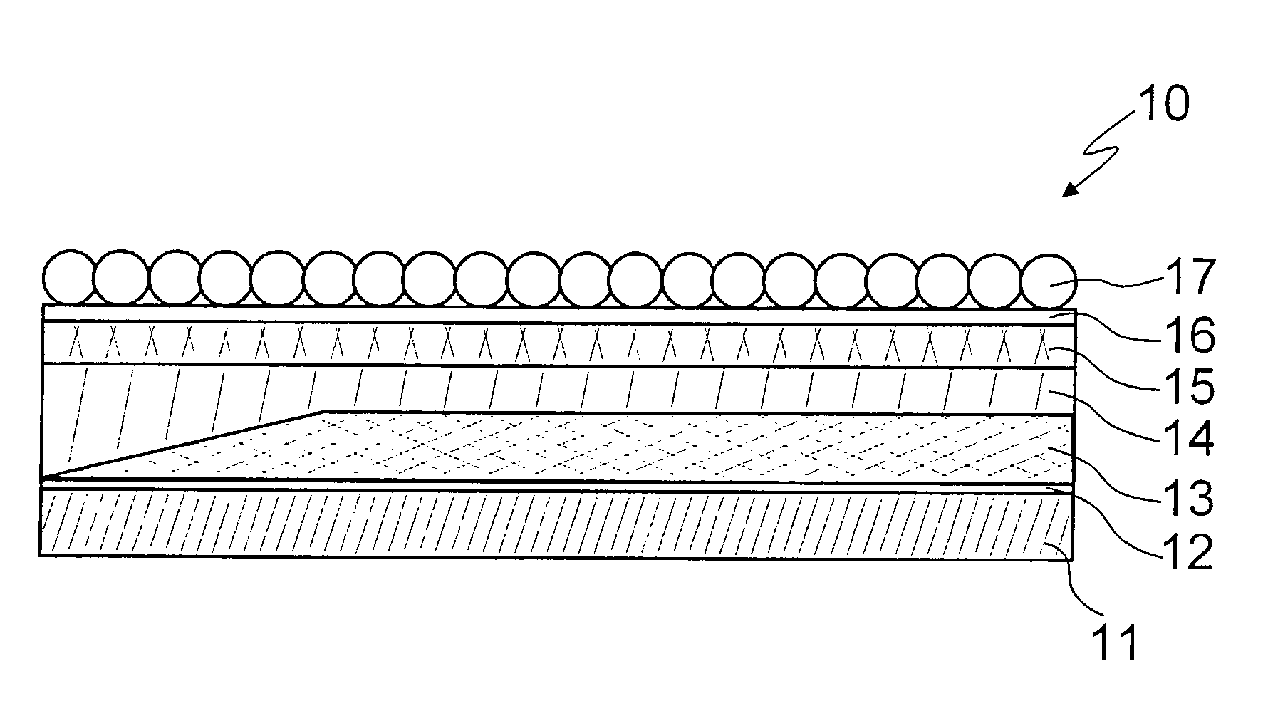
[0018]FIG. 1 shows an ignition coil 10, which is part of an ignition system of a motor vehicle, spark-ignition engine not shown here in further detail.

[0019]Ignition coil 10 includes a coil core 11, which is made of iron or a core stack and is surrounded by a first coil shell 12 that forms the so-called secondary coil shell. Positioned on secondary coil shell 12 is a first coil winding 13, which forms the so-called secondary winding and is made out of insulated copper wire, and of which one end is connected to a high-voltage terminal of ignition coil 10, the high-voltage terminal being connectible, in turn, to a spark plug. The other end of secondary winding 13 is connected to ground.

[0020]Secondary winding 13 is surrounded by an electrically insulating, encapsulating material 14, which constitutes a supporting material for a second coil shell 15 that forms the so-called primary coil shell.

[0021]An electrically conductive coating 16 is applied to primary coil shell 15. Coating 16 is...


PUM

PropertyMeasurementUnit
electrically conductiveaaaaaaaaaa
lengthaaaaaaaaaa
magnetic couplingaaaaaaaaaa

Abstract

An ignition coil for an internal combustion engine, including a magnetically active core, a first coil shell which is used as a support for a first coil winding made of an electrically conductive wire, and a second coil shell which is positioned so as to be concentric to the first coil shell and is used as a support for a second coil winding made of an electrically conductive wire. Situated between the first coil winding and the second coil winding is a shielding layer, which is made of an electrically conductive material and provided with a grounding contact.

Description

FIELD OF THE INVENTION[0001]The present invention relates to an ignition coil for an internal combustion engine, in particular for an internal combustion engine of a motor vehicle.BACKGROUND INFORMATION[0002]An ignition coil is known to be in practical use and takes, for example, the form of a so called rod-type ignition coil of a spark-ignition engine of a motor vehicle.[0003]An ignition coil represents an energy-transmitting, high-voltage source used in a spark-ignition engine for controlling at least one spark plug, whose electrodes are inserted into a combustion chamber of the internal combustion engine, and which is used for igniting a fuel mixture introduced into the combustion chamber, whereby a movement of an engine piston and, therefore, of an engine crankshaft is initiated.[0004]A conventional type of ignition coil has two concentric windings, which have different numbers of turns per unit length and are magnetically coupled to each other. The magnetic coupling is strength...

Claims


Application Information

Patent Timeline
Patent Type & Authority Patents(United States)
IPC IPC(8): H01F27/02H01F27/28H01F27/32H01F27/36H01F38/12
CPCH01F38/12H01F27/367H01F27/288H01F27/323H01F27/327H01F27/36H01F27/363
Inventor FISCHER, BERNDWEIMERT, MARKUSLINDENTHAL, KONSTANTINSKOWRONEK, TIM
Owner ROBERT BOSCH GMBH
Why Eureka
Try Eureka