Optical module and optical transmission device

a technology of optical modules and optical transmission devices, applied in the direction of optical elements, instruments, optical waveguide light guides, etc., can solve the problems of degrading coupling efficiency, narrow space between mounting parts, and difficult optical axis alignment, so as to improve coupling efficiency and facilitate optical axis alignment of surface light emitting elements and optical waveguides. , the effect of low cos

Inactive Publication Date: 2007-01-30
FUJIFILM BUSINESS INNOVATION CORP
View PDF15 Cites 13 Cited by
  • Summary
  • Abstract
  • Description
  • Claims
  • Application Information

AI Technical Summary

Benefits of technology

[0011]The present invention has been made in view of the above circumstances. The present invention provides an optical module and an optical transmission device using the same optical module, in which the optical axis alignment of a surface type light emitting element and an optical waveguide is easy and with which the longtime reliability of coupling efficiency of the optical module with respect to an optical transmission medium is realized. Further, the present invention provides a low cost optical transmission module, which houses mounting parts such as an optical element and an optical waveguide and with which electrical connections within the module can be performed easily, the design freedom is high and the cost reduction of the optical transmission module is possible.
[0012]Further more, the present invention provides an optical transmission module, which houses mounting parts such as an optical element and an optical waveguide and with which thermal influence of bonding wires is restricted and a high reliability is obtained even at high speed operation.

Problems solved by technology

However, since, in the first related art, an optical module, the other end of the optical waveguide is not fixed, there is a problem that an optical axis is deviated by a change with the passage of time, resulting in degradation of coupling efficiency.
In addition thereto, there is a problem that the optical axis alignment is difficult.
In the second related art, the optical transmission module, there is a problem that a space between mounting parts is narrowed due to miniaturization of the module and bonding wires for connecting the optical element to electrode pins for external connection obstruct a front area of the light emitting element.
In particular, since the optical waveguide is three dimensional and the size thereof is large, arranging routes of the bonding wires are obstructed by the optical waveguide.
Therefore, there is a threat that the wiring bonding becomes difficult or impossible.
Further, when the arrangement of the bonding wires is preferential, there are problems that the configuration of the optical transmission module is restricted, the design freedom is degraded and the fabrication cost is increased.

Method used


Image

  • Optical module and optical transmission device
  • Optical module and optical transmission device
  • Optical module and optical transmission device

Examples


first embodiment

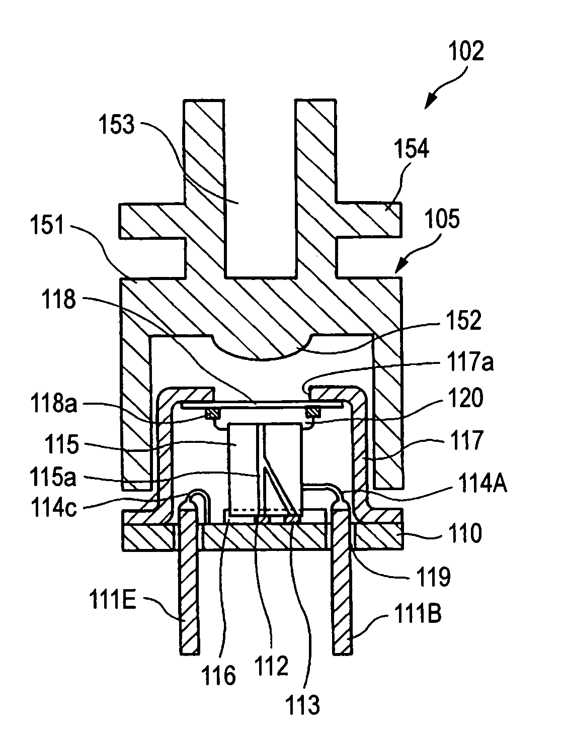
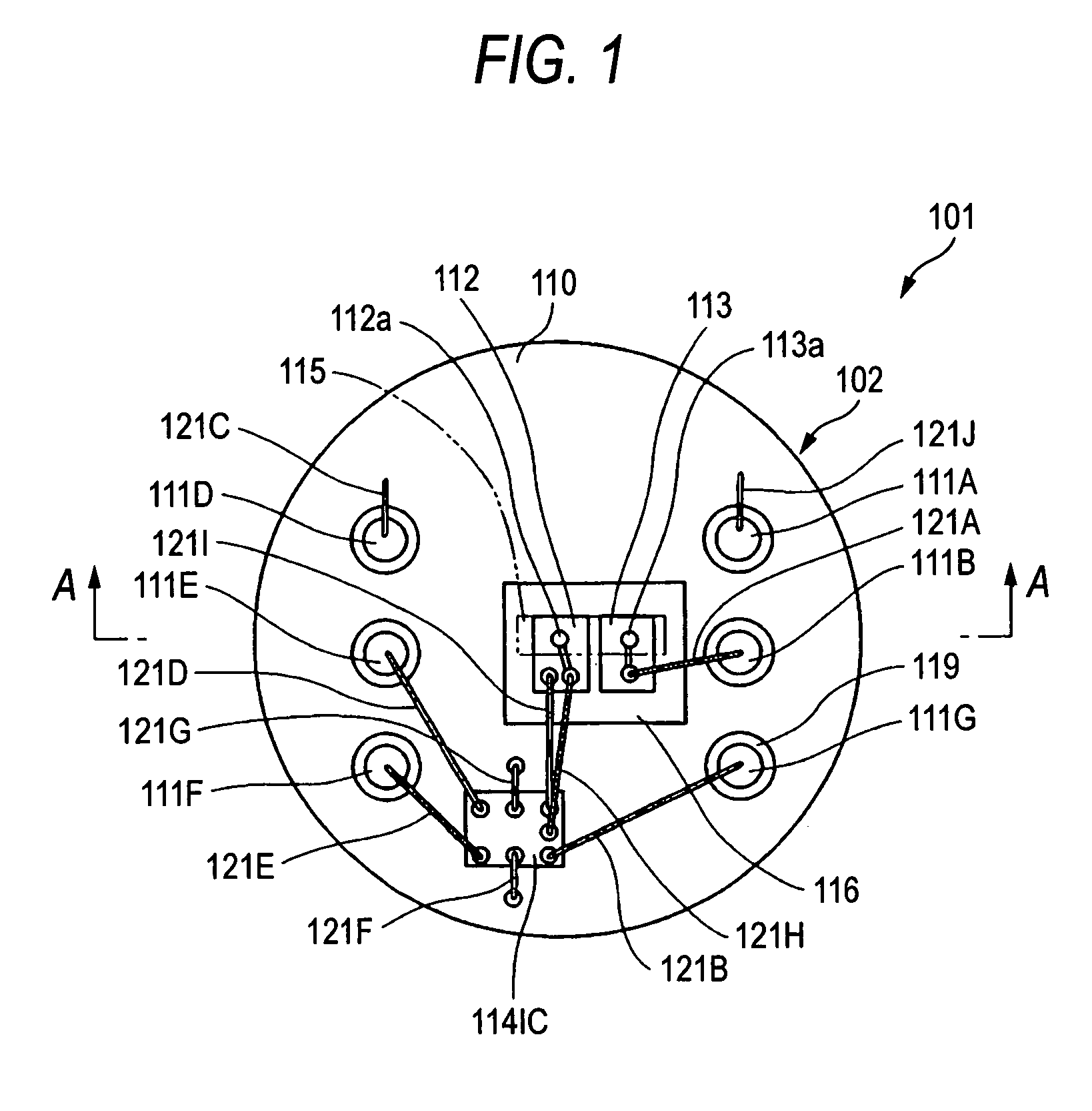
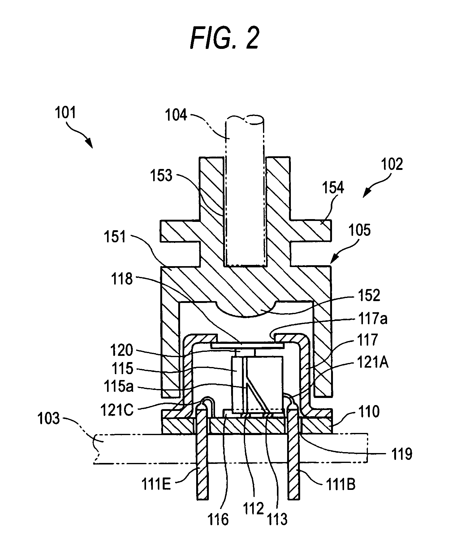
[0033]FIG. 1 is a plan view of an optical transmission device according to a first embodiment of the present invention and FIG. 2 is a cross sectional view taken along a line A—A in FIG. 1.

[0034]The optical transmission device 101 is configured by an optical module 102, to which an optical fiber 104 is connected as an optical transmission medium, and a circuit board 103, on which the optical module 102 is mounted.

[0035]The optical module 102 includes a metal stem 110 as a base portion, a light receiving element 112 and a light emitting element 113 provided on the metal stem 110 as a surface type optical element, an IC 114 for amplifying an output signal of the light receiving element 112, an optical waveguide 115 optically coupled with the light receiving element 112 and the light emitting element 113, a sub mount 116 as a fixing member for positioning and holding the light receiving element 112, the light emitting element 113 and the optical waveguide 115, a metal cap 117 having an...

second embodiment

[0060]FIG. 5 shows an optical module according to the second embodiment of the present invention. The second embodiment is similar to the optical module 102 of the first embodiment except that a gel-type refractive index matching agent is used as the fixing member 120 and the fixing member 120 fills a space between the cap 117 and the optical waveguide 115.

[0061]The gel-type refractive index matching agent may be, for example, gel-type silicone resin. The gel-type refractive index matching agent has refractive index similar to that of the optical waveguide 115 and the transparent window 118 and a different in refractive index between the fixing member 120 and the optical waveguide 115 and the transparent window 118 is preferably within 0.1 in view of the transmission loss due to Fresnel reflection. It is more preferable that the difference is within 0.05. Since the gel-type refractive index matching agent is a jelly, it is possible to obtain an enough adhering force with respect to ...

third embodiment

[0063]FIG. 6 shows an optical module according to the third embodiment of the present invention and FIGS. 7A, 7B shows the position and configuration of the fixing member shown in FIG. 6. As shown in FIGS. 6, 7A, and 7B, the third embodiment is substantially the same as the optical module 102 of the first embodiment except that the fixing member 120 of the third embodiment is an elastic member and is provided in a position in the vicinity of the center portion of the end face of the optical waveguide 115 and spaced apart from the position of the light guide portion 115a.

[0064]As the elastic member, transparent silicon rubber may be used. The elastic member has a circular configuration as shown in FIG. 7A or an ellipsoidal configuration as shown in FIG. 7B. In either case, the fixing member 120 is arranged such that it exerts elastic force (pressing force) on the optical waveguide 115 and the transparent window 118.

[0065]The elastic member may be provided on the side of the optical ...


PUM


Abstract

An optical module includes a base portion; a surface type optical element receiving or emitting light; an optical waveguide being mounted on the base portion; a holding member being mounted on the base portion; a cap being mounted on the base portion; and a fixing member. The optical waveguide includes on an end portion of the optical waveguide light input / output end face that transmits light therebetween. The holding member positions and holds the surface type optical element and one end portion of the optical waveguide. The cap includes a light transmitting window provided in a position opposing to the other end portion of the optical waveguide. The cap at least partially covers the optical element and the optical waveguide. The fixing member fixes the other end portion of the optical waveguide and the cap.

Description

CROSS-REFERENCE TO RELATED APPLICATIONS[0001]This application is based on and claims the benefit of priority from the prior Japanese Patent Applications No. 2005-259586, filed on Sep. 7, 2005, and No. 2005-269526, filed on Sep. 16, 2005; the entire contents of which are incorporated-herein by reference.BACKGROUND OF THE INVENTION[0002]1. Field of the Invention[0003]The present invention relates to an optical module and an optical transmission device for performing an optical communication by using an optical element portion, which includes a light emitting element and a light receiving element, and an optical waveguide.[0004]2. Description of the Related Art[0005]In first related art, a low cost optical transmission device using surface type optical elements such as a surface emitting laser (VCSEL) and a photodiode (PD), which have a light receiving / emitting portion on a side opposite to a mounting surface thereof, is known and, in order to realize downsizing, cost reduction and hig...

Claims


Application Information

Patent Timeline
Patent Type & Authority Patents(United States)
IPC IPC(8): G02B6/12G02B6/26G02B6/36
CPCG02B6/4204H01L2224/48137
Inventor SAKAI, KAZUHIROUENO, OSAMUOHTANI, OSAMU
Owner FUJIFILM BUSINESS INNOVATION CORP
Why Eureka
Try Eureka