Envelope limiting for polar modulators

a polar modulator and envelope technology, applied in the field of communication transmitters, can solve the problem that the limiting operation affects performance only slightly, and achieve the effect of improving the efficiency of the polar modulator of the radio transmitter

Active Publication Date: 2007-01-30
QUINTIC MICROELECTRONICS WUXI
View PDF6 Cites 21 Cited by
  • Summary
  • Abstract
  • Description
  • Claims
  • Application Information

AI Technical Summary

Benefits of technology

[0009]In one embodiment, a radio transmitter is provided that comprises a control circuit for improving the efficiency of the radio transmitter's polar modulator. The control circuit comprises logic to set amplitude modulation data to an upper threshold level when a modulation signal exceeds t

Problems solved by technology

The limiting operation affects performance only slightly since it occurs infreque

Method used


Image

  • Envelope limiting for polar modulators
  • Envelope limiting for polar modulators
  • Envelope limiting for polar modulators

Examples


Embodiment Construction

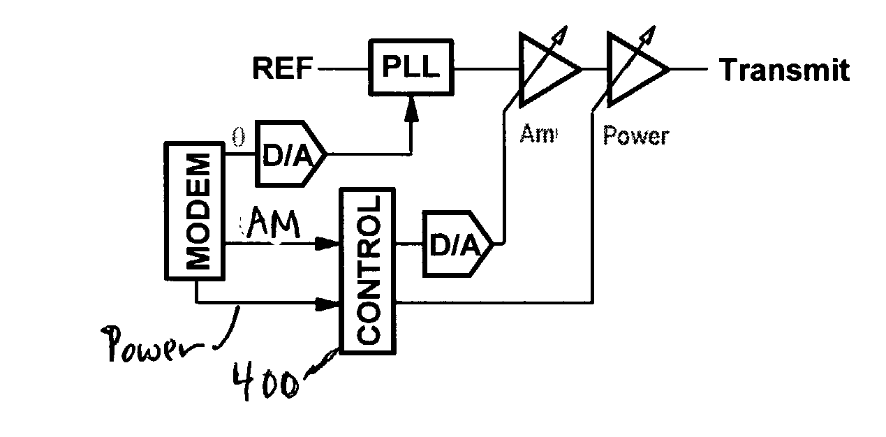
[0017]The present invention includes a system that intelligently compresses the amplitude modulation in polar modulators so that it can be implemented with a single-stage variable gain amplifier.

[0018]In one embodiment, the present invention intelligently limits the amplitude modulation signal by “clipping” its peaks and / or “softening” its nulls to allow envelope control by a single variable gain amplifier stage.

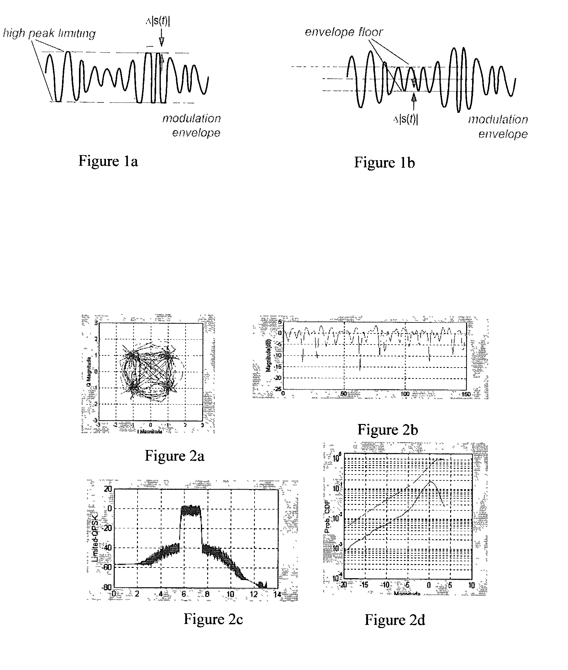
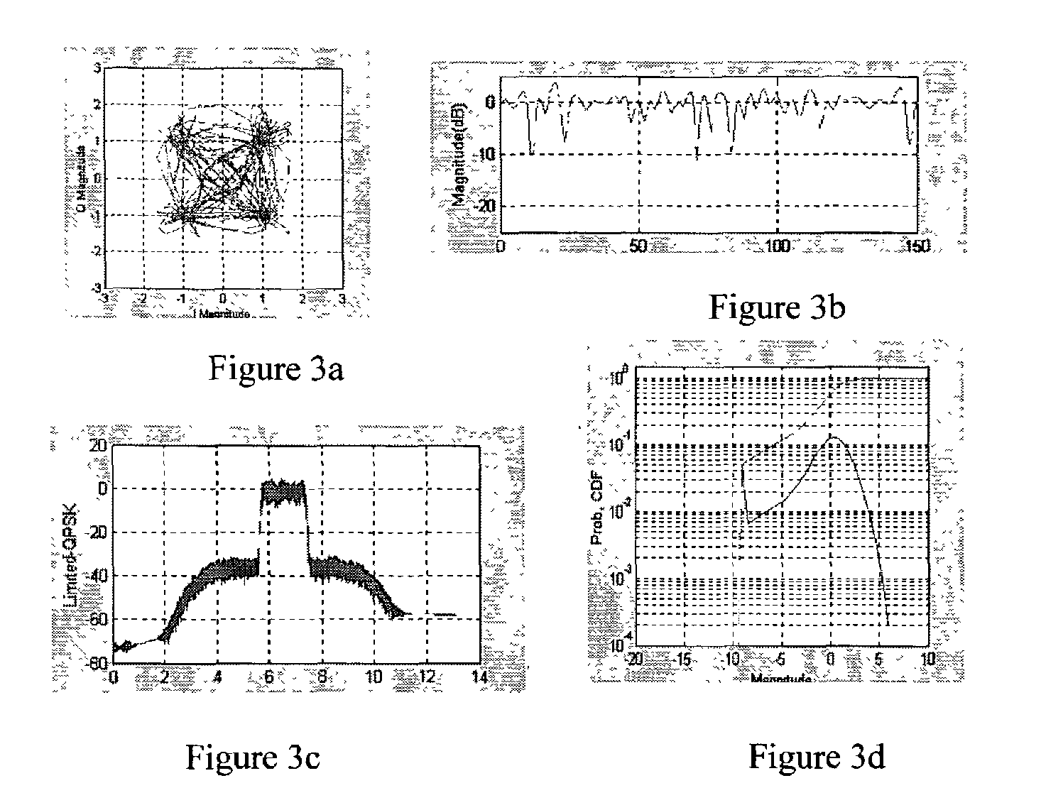
[0019]FIGS. 1a and 1b illustrate envelope limiting in accordance with the present invention. Clipping the amplitude modulation signal restricts the maximum level of the transmit signal's envelope and introduces distortion but also improves system efficiency since this allows the transmitter to operate at lower DC power levels. Preferably, the clipping is generally limited to a few dB or less to avoid severely affecting the transmit signal. FIG. 2 illustrates the effects of 2 dB limiting on the FIR-filtered QPSK-modulated modulated signal. For example, FIGS. 2a–d show (a) a c...


PUM


Abstract

Envelope limiting for a polar modulator. A system is provided that intelligently compresses the amplitude modulation in a polar modulator so that it can be implemented with a single-stage variable gain amplifier. Limiting the amplitude modulation range on the low side prevents collapse of the transmit signal's time-varying envelope and eases circuit implementation. Limiting the amplitude modulation range on the high side reduces the peak-to-average ratio of the waveform and thereby improves the efficiency of the radio transmitter.

Description

CROSS REFERENCE TO RELATED APPLICATIONS[0001]This Application claims the benefit of priority of a pending U.S. Provisional Patent Application entitled “ENVELOPE LIMITING FOR POLAR MODULATORS” Ser. No. 60 / 307,346 filed on Jul. 23, 2001, the disclosure of which is incorporated by reference herein in its entirety for all purposes.FIELD OF THE INVENTION[0002]The present invention relates generally to communication systems, and more particularly, to a communication transmitter using digital modulation with a time-varying envelope.BACKGROUND OF THE INVENTION[0003]Modem communications systems increasingly rely on digital modulation techniques for reliable system performance. These techniques modulate a carrier signal by varying its phase and / or amplitude.[0004]The heterodyne architecture is standard for radio transmitters. It uses rectangular (in-phase and quadrature-phase) data and I / Q modulation to generate the transmit signal. This architecture handles phase and amplitude modulation equ...

Claims


Application Information

Patent Timeline
IPC IPC(8): H04B1/02H03C3/38H03C5/00H03F1/02H03G3/30H03G7/06H04B1/04H04L27/36
CPCH03C5/00H03F1/02H03G3/3042H04L27/361H03G7/06H04B2001/0408H04B2001/045H03F3/24
Inventor GROE, JOHN B.HARDIN, CARL THOMASSHEBA, MAHBUBA
Owner QUINTIC MICROELECTRONICS WUXI
Why Eureka
Try Eureka