

Diamond film depositing apparatus using microwaves and plasma
a depositing apparatus and plasma technology, applied in the direction of coatings, electric discharge lamps, electric lighting sources, etc., can solve problems such as not being commercialized, and achieve the effect of improving the concentration of microwaves
- Summary
- Abstract
- Description
- Claims
- Application Information
AI Technical Summary
Benefits of technology
Problems solved by technology
Method used
Image

Examples
first embodiment
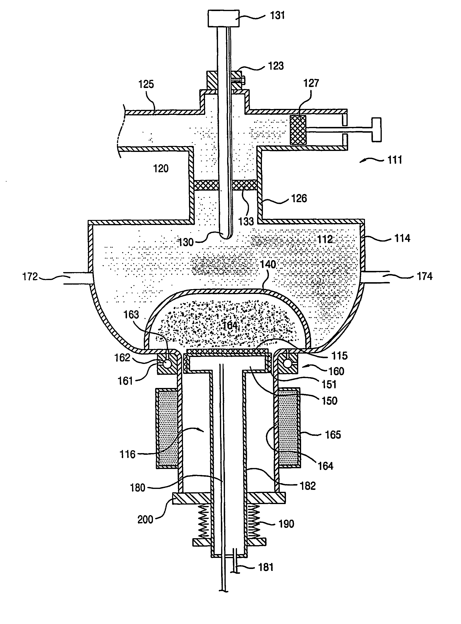
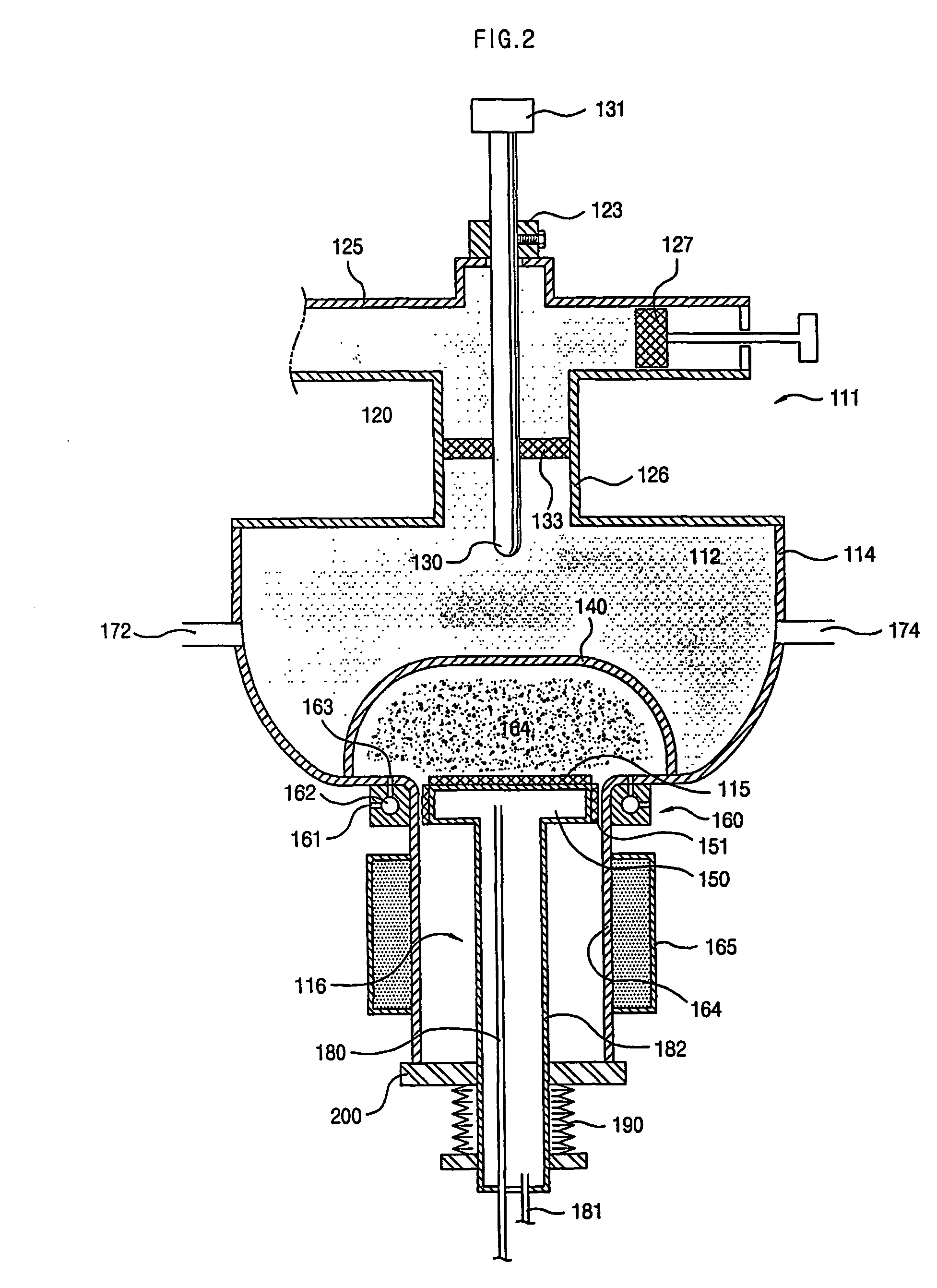
[0037]FIG. 2 is a cross section showing a diamond film depositing apparatus using microwaves and plasma in accordance with the present invention. The diamond film depositing apparatus of the present invention is comprised of a rectangular wave guide 125, a mode transition coupler 120, an antenna rod 130, a quartz bell jar 140, a workpiece holder 116, a microwave cavity resonator 112, a source gas inflow ring 160, a mechanical support cylinder 164, a cooling jacket 165, gas inflow and outflow conduits 172 and 174 and a vacuum seal 190.
[0038]All the elements are described in more detail, hereinafter.
[0039]The mode transition coupler 120 serves to convert the square mode of electromagnetic waves into the circular transfer electromagnetic mode of microwaves. Electromagnetic impedance matching with the mode transition coupler 120 can be accomplished by adjusting the position of a short block 127 that is capable of moving through the region of the rectangular wave guide 125.
[0040]The ante...
second embodiment
[0054]FIG. 4b is a view showing the distribution of the powers of electromagnetic waves for a stepped barrel-shaped cavity resonator (refer to FIG. 3) in accordance with the present invention. In comparison with the conventional cylindrical cavity resonator (shown in FIG. 4a), a power peak 142b in the vicinity of a probe or antenna rod (in the upper portion of the cavity of the resonator) is weakened, while another power peak 141b in the vicinity of a workpiece holder, on which a workpiece is situated, is somewhat strengthened.
[0055]FIG. 4c is a view showing the distribution of the powers of electromagnetic waves for a hemispheric cavity resonator (refer to FIG. 2) in accordance with the first embodiment of the present invention. In comparison with the conventional cylindrical cavity resonator (shown in FIG. 4a), a power peak in the vicinity of a probe or antenna rod (in the upper portion of the cavity of the resonator) is considerably weakened and scarcely visible, while a power pe...
third embodiment
[0059]In accordance with the present invention, a microwave cavity resonator 112, as shown in FIG. 5, is a combination of an upper cylindrical portion and a lower truncated cone-shaped portion. The microwave cavity resonator 112 has this type of shape, so microwaves, as deduced from FIGS. 4a to 4c, are concentrated in the lower portion of the resonator, that is to say, the interior of the quartz bell jar to which plasma is discharged.
INDUSTRIAL APPLICABILITY
[0060]As described above, the present invention provides a diamond film depositing apparatus, which is capable of improving electromagnetic waves-plasma power coupling efficiency by fabricating its cavity resonator in the form of a hemisphere or stepped barrel reduced in diameter in a downward direction. In consequence, the power of microwaves can be concentrated on a portion in which plasma is generated, that is to say, a workpiece, and can enlarge a deposition area by actually increasing the volume of plasma.
[0061]In addition, ...
PUM
| Property | Measurement | Unit |
|---|---|---|
| Diameter | aaaaa | aaaaa |
| Shape | aaaaa | aaaaa |
Abstract
Description
Claims
Application Information