

Signal transmission system
a transmission system and signal technology, applied in the field of signal transmission systems, can solve the problems of excessive computation and difficult architecture, and achieve the effect of simple architectur
- Summary
- Abstract
- Description
- Claims
- Application Information
AI Technical Summary
Benefits of technology
Problems solved by technology
Method used
Image

Examples
Embodiment Construction
[0050]The following is a description of the embodiments of the present invention based on the accompanying drawings. It is to be noted that in all of the drawings for describing these embodiments, the same elements are assigned the same numerals and repeated descriptions thereof are omitted.
[0051]This embodiment is described as example of the signal transmission system of the present invention in the following order: 1. The LSI Chip I / O Driver and Receiver Circuit Configuration; and 2. The System Structure.
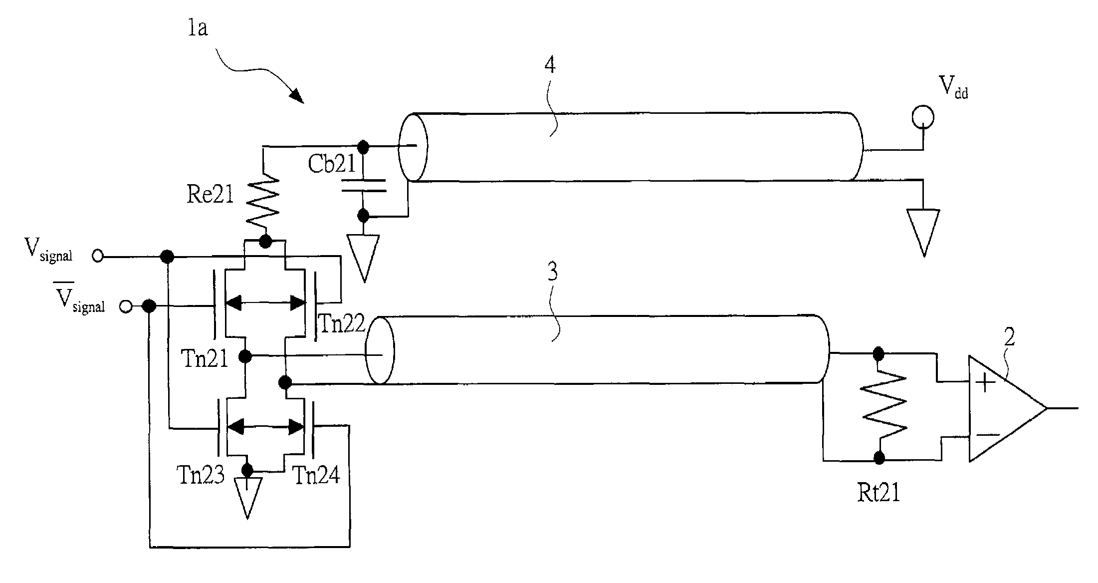
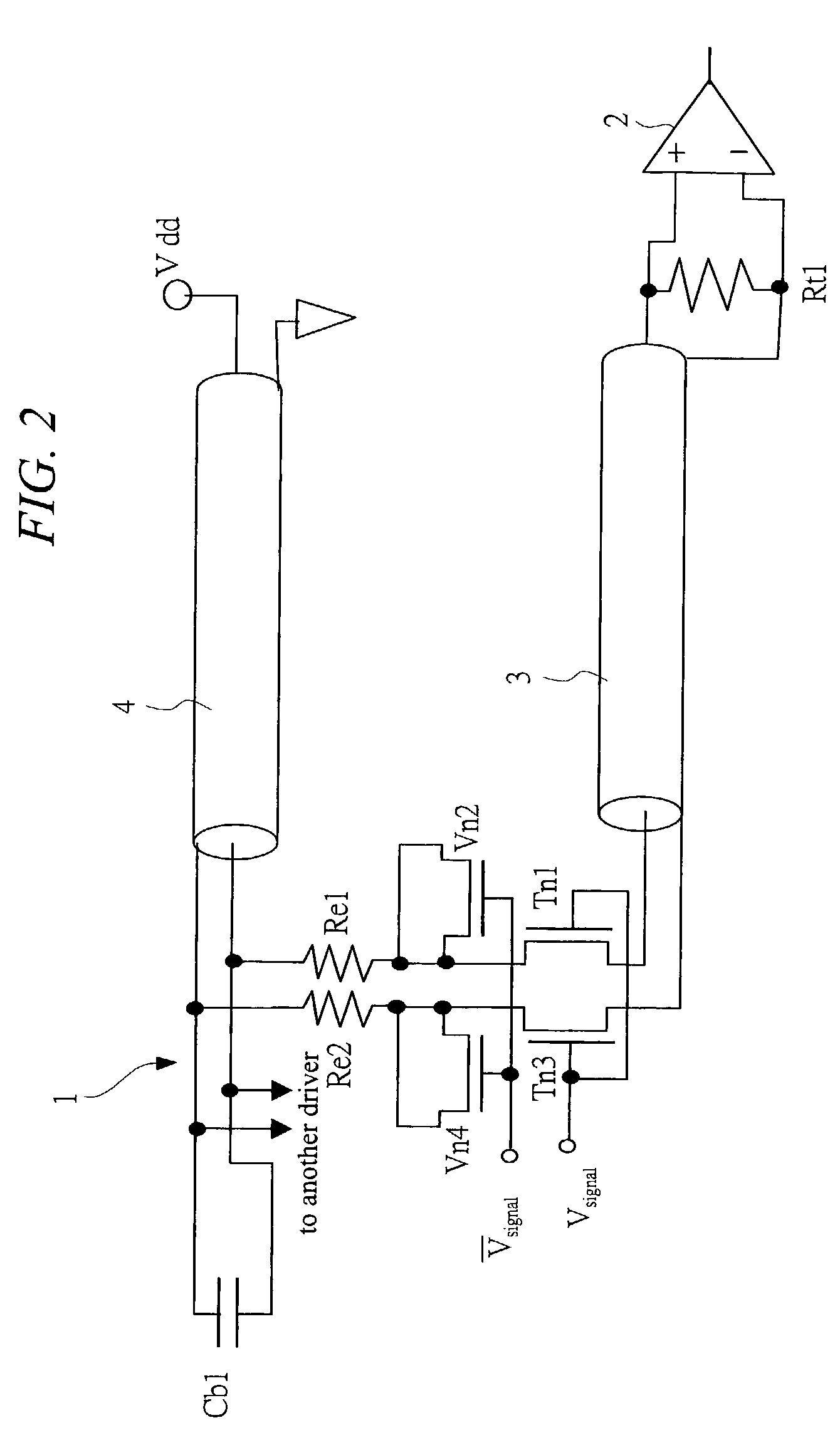
1. The LSI Chip I / O Driver and Receiver Circuit Configuration
[0052]The following structures which were previously proposed by the inventors of the present invention may be favorably used for the I / O driver and receiver circuit structure of the LSI Chip: the circuit structure including a power source and ground pair of P1 (Japanese Patent Application Laid-Open No. 11-284126) and P2 (Japanese Patent Application Laid-Open No. 2000-174505); the receiver structure of P4 (Japanese Paten...
PUM
 Abstract
Description
Claims
Application Information