
Automatic sampler and needle for the same

a sampler and needle technology, applied in the field of automatic sampler and needle, can solve the problems of cross contamination, though slight in some cases, and the inability to easily remove the sample component once adsorbed chemically, and achieve the effects of reducing chemical adsorption, reducing chemical activity, and superior chemical resistan

Inactive Publication Date: 2007-02-13
SHIMADZU CORP
View PDF62 Cites 8 Cited by
  • Summary
  • Abstract
  • Description
  • Claims
  • Application Information

AI Technical Summary

Benefits of technology

[0017]In order to attain the foregoing object, an automatic sampler according to the present invention comprises a needle which is subject to a surface treatment for reducing chemical adsorption. More specifically, the needle of the present invention contains a base metal, and the surface of the needle is coated with a coating material which is lower in chemical activity than the chemical activity of the base metal of the needle. In one embodiment, the surface of the needle is plated with a noble metal, such as gold or platinum. Alternatively, the surface of the needle may be coated with synthetic resin such as PEEK which is superior in chemical resistance. Further, a quartz thin film may be formed on the surface of the needle. Moreover, a non-noble metal may be plated or deposited on the surface of the needle. The automatic sampler of the present invention is preferably used for a liquid chromatography. It is possible to obtain a practically sufficient antifouling effect, even against contamination coming from chemical adsorption which cannot be removed sufficiently by related-art measures against physical contamination. Thus, it is possible to provide an automatic sampler which can perform highly sensitive analysis.

Problems solved by technology

The sample component once adsorbed chemically cannot be removed easily, even if it is vigorously rinsed with organic-solvent-based detergent.
Thus, cross contamination is, though slightly in some cases, brought about.

Method used


Image

  • Automatic sampler and needle for the same
  • Automatic sampler and needle for the same
  • Automatic sampler and needle for the same

Examples


Embodiment Construction

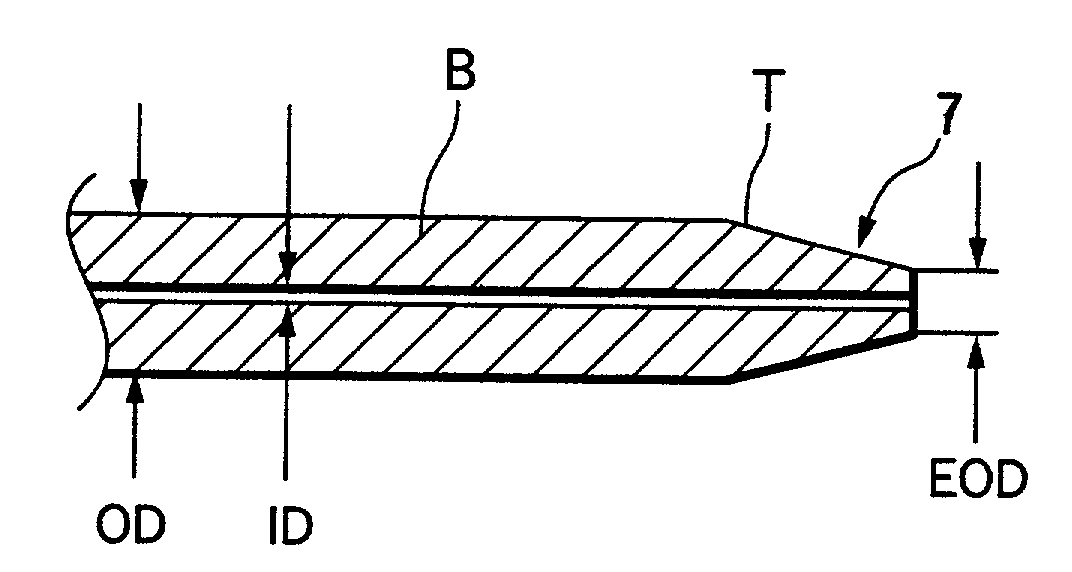
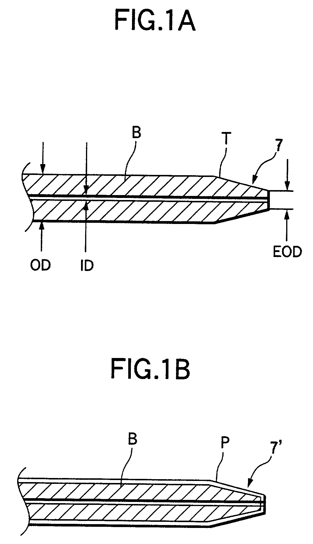
[0023]FIGS. 1A and 1B show needles according to first and second embodiments of the invention, respectively.

[0024]The needle 7 shown in FIG. 1A is a flat-head needle with an outer diameter OD of 1.2 mm and an inner diameter ID of 0.5, and a flat end with an outer diameter EOD of 0.65 mm. Base metal B is a stainless steel, and the surface of the base metal B is coated with a platinum-plated layer T having a thickness of several micrometers (μm). The surface of the needle is covered with the platinum-plated layer T which is much lower in adsorptive activity than stainless steel. Therefore, when the needle 7 is used for the automatic sampler shown in FIG. 4, chemical adsorption on the surface of the needle 7 is restrained, which in turn reduces cross-contamination.

[0025]In the needle 7′ shown in FIG. 1B, base metal B is coated with a synthetic resin coating P (about 300 μm thick) instead of the metal plating used in the first embodiment. The synthetic resin coating P in this second emb...


PUM

PropertyMeasurementUnit
outer diameter EODaaaaaaaaaa
outer diameter ODaaaaaaaaaa

Abstract

The surface of a needle for collecting samples is coated with a coating material lower in chemical activity than a base metal of the needle. More specifically, the surface of the needle may be coated with a layer of gold or platinum. Alternatively, the surface of the needle may be coated with a synthetic resin coating of, for example, PEEK which is superior in chemical resistance. As a result, it is possible to obtain a practically sufficient antifouling effect even on contamination coming from chemical adsorption. Such contamination could not be removed sufficiently only by related-art measures against physical contamination. Thus, it is possible to provide an automatic sampler which can perform highly sensitive analysis.

Description

BACKGROUND OF THE INVENTION[0001]1. Field of the Invention[0002]The present invention relates to an automatic sampler and a needle of the automatic sampler for an analyzer which performs liquid analysis, such as a liquid chromatograph. More particularly, the needle is subject to a surface treatment or coating which reduces contamination of the needle caused by chemical adsorption.[0003]2. Description of the Related Art[0004]FIG. 4 shows an example of a main portion of a flow path arrangement of an automatic sampler for a liquid chromatograph.[0005]In the automatic sampler shown in FIG. 4, a plunger 3 is designed to perform a reciprocating motion by mechanical force. A liquid sample to be analyzed is stored in a large number of vials (small-volume sample bottles) 8 in advance. The vials 8 are arranged on a rack 81. A needle 7 collects samples from the vials 8. The needle 7 is connected to an injector valve 1 through a looped flexible pipe (hereinafter referred to as “loop”) 6. In add...

Claims


Application Information

Patent Timeline
Patent Type & Authority Patents(United States)
IPC IPC(8): B01L3/02G01N30/18G01N35/10G01N30/24G01N35/00
CPCB01L3/021G01N2035/00277G01N30/24G01N30/18
Inventor TATSUMI, NOBUYUKI
Owner SHIMADZU CORP
Learn More