Electrical power distribution and communication system for an underwater cable

a technology of electrical power distribution and communication system, applied in the direction of cables, insulated conductors, instruments, etc., can solve the problems of high inefficiency of battery maintenance process, frequent undesirable use of batteries as primary power sources, and unwanted downtime, so as to enhance the reliability of seismic streamer cable assemblies and improve structure and/or operation

Active Publication Date: 2007-02-13
INPUT OUTPUT INC
View PDF45 Cites 297 Cited by
  • Summary
  • Abstract
  • Description
  • Claims
  • Application Information

AI Technical Summary

Benefits of technology

[0014]A principal object of the present invention is to provide a power distribution and / or data communication system which provides an elegant and reliable power distribution and data communication system for supplying power and data to a plurality of electrical devices disposed along an underwater cable. The power distribution and / or data communication system may also provide an improved structure and / or operation which enhances the reliability of the seismic streamer cable assembly even when the cable is damaged and / or electrical devices are removed.
[0015]Additional objects of various aspects of the present invention include providing an underwater cable structure which enables the transferring of operational power to the electrical devices without breaching the outer sheath of the underwater cable; eliminating batteries as the primary source of operational power for the electrical devices coupled to the underwater cable; eliminating and / or reducing the need to change batteries; providing better economy by enabling an underwater cable assembly to survey for more hours without interruptions; extending the operational length of underwater cables by 5, 10, 15, 20 km or more without altering the basic structure and / or operation of the underwater cable power distribution and / or data communication system; increasing the bandwidth of data transmitted to and received from the electrical devices; minimizing the weight of wires (e.g., copper wires) in the underwater cable; reducing the weight, size, and number of inductive cores used along the underwater cable; allowing brittle cores to be used in inductors along the underwater cable; increasing the power transfer efficiency from a main power supply to the electrical devices disposed along the underwater cable; reducing noise generated by the power transfer which may interfere with the seismic equipment; reducing capacitive coupling and mutual inductance between the electrical devices and other parts of the underwater cable; improving the coupling coefficient of a transformer disposed about the outer sheath of the underwater cable; providing a fault tolerant power distribution and data communication system in an underwater cable assembly; reducing the number of data and power transmission lines coupled to each of the electrical devices and disposed in the underwater cable; reducing the latency time associated with communications through the underwater cable with the electrical devices; allowing the electrical devices to respond directly to detected fault conditions without intervention of dry-end electronics; and providing for degraded mode operations which allow the most critical electrical device operations to be maintained even during fault conditions.

Problems solved by technology

However, the use of batteries as the primary power source is frequently undesirable since the batteries may require replacement every few weeks or months.
This battery maintenance process may be highly inefficient and results in unwanted down time.
Further, when lithium batteries are used, the cost of disposal and replacement of the batteries for a single vessel may exceed several hundred thousand dollars per year.
Accordingly, conventional wet unit designs suffer from a number of problems.
A major problem associated with eliminating batteries from the wet unit devices is the low coupling coefficient between the wet units and the underwater cable.
Although numerous attempts have been made to improve this coupling coefficient, these attempts have been less than satisfactory.
However, due to a number of technical difficulties, a seismic streamer cable assembly which transfers operational power from the underwater cable directly to the wet units or to the wet units and in-streamer devices has not yet proven commercially practical.
Transmission line losses in transmission lines of underwater streamer cables having a length longer than 6 km exacerbate the problems associated with powering the spaced electrical devices directly from the underwater streamer cable.
Furthermore, data and / or power transmitted to electrical devices at the aft end of an underwater streamer cable are often severely attenuated.
This problem may be particularly acute where data lines are also utilized to transmit power.
It has been found that transmission line losses and noise levels in such a system often make the system commercially impractical.
Thus, communication with and power delivery to aft electrical devices may be difficult, particularly for ever increasing cable lengths.
Much research has been directed at solving this problem, but to date there has been little success.
However, this is typically unacceptable because additional weight may be added to the underwater cable and because higher power levels may interfere with the operations of the seismic equipment, such as the underwater hydrophones.
If an electrical device fails, falls off, or is otherwise damaged or removed from the underwater cable, the associated coil on the transmission line may have an open secondary, detuning the tuned circuit.
Often, the transmission line may be detuned to the point where reliable data and power transfer is compromised.
In typical underwater sonar cables, it is difficult to transfer power along the cable at a high frequency due to the length of the cable, amount of power required to be distributed, and the noise generated by such a transfer.
However, low frequency signals are extremely inefficient when coupled across a transformer having a low coupling coefficient.
Thus, configurations which couple power from the main power line may be commercially impractical in many applications.
Another shortcoming of conventional streamer power distribution and / or data communication systems may be reliability problems due to the leakage of seawater into one or more of the sections of the streamer cable.
When the transmission line is disabled, sensor data cannot be collected, the electrical devices cannot be powered from the underwater cable, and depth control from the survey vessel may be precluded.

Method used


Image

  • Electrical power distribution and communication system for an underwater cable
  • Electrical power distribution and communication system for an underwater cable
  • Electrical power distribution and communication system for an underwater cable

Examples


Embodiment Construction

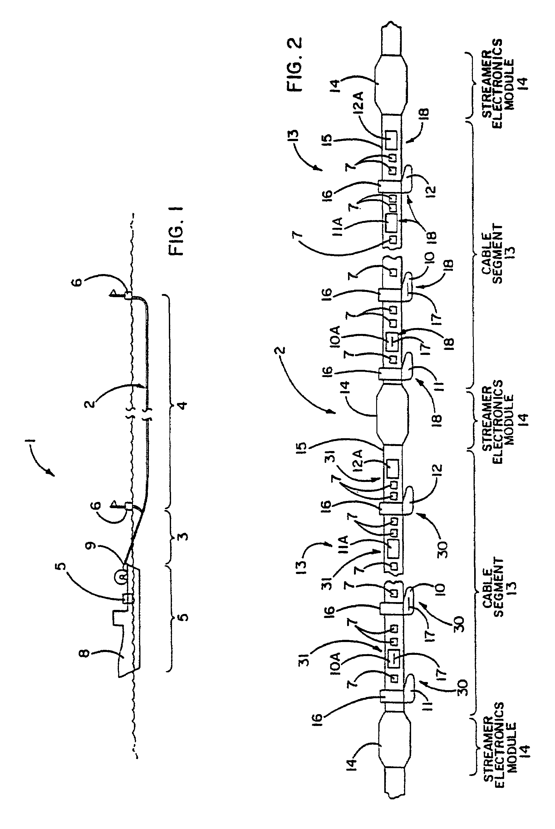
[0112]Referring to FIGS. 1 and 2, a typical marine seismic data acquisition system 1 may include a survey vessel 8 which tows one or more underwater streamer cables such as underwater cable 2. The underwater cable 2 may include one or more sections such as lead-in section and underwater section 4. The lead-in section 3 is typically connected between the underwater section 4 and dry-end electronics 5. The dry-end electronics 5 are typically disposed on the survey vessel 8 and may include a plurality of data acquisition, processing, storage, and control devices. In some embodiments, it may be desirable to couple first and second ends of the underwater section 4 to first and second buoys 6, respectively.

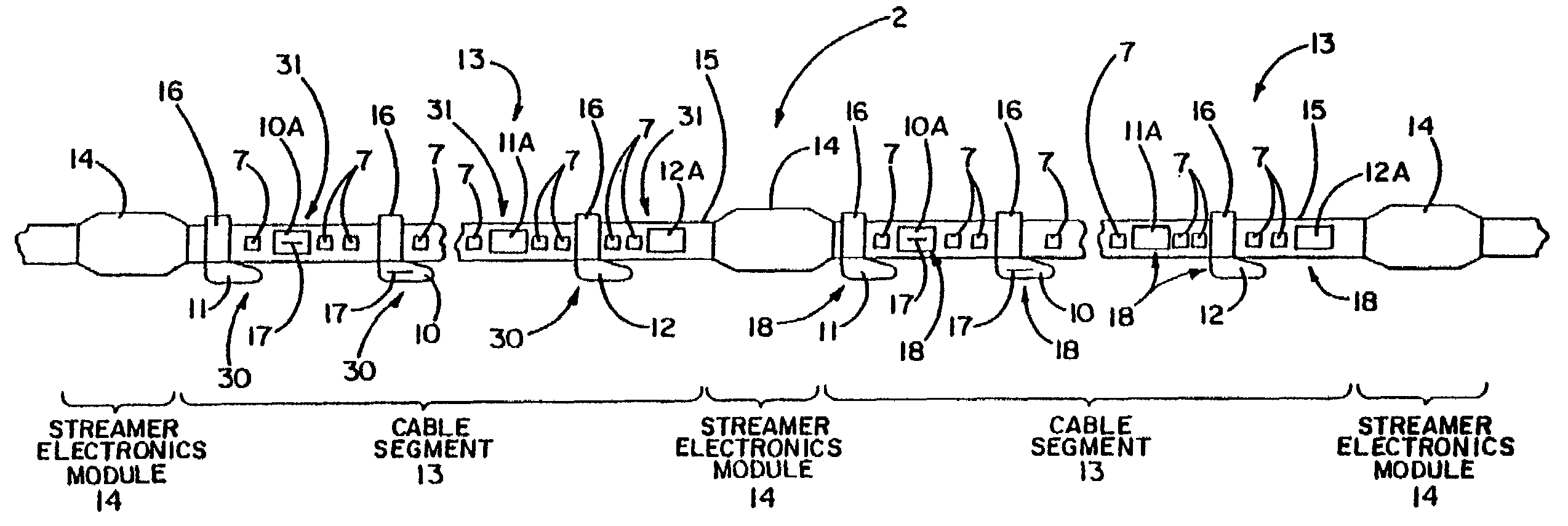
[0113]The underwater cable 2 may be a continuous streamer cable or be discontinuous and divided into a plurality of cable segments. For example, FIG. 2 shows a portion of an underwater cable 2 which may be divided into a plurality of cable segments 13 by a plurality of streamer electron...


PUM


Abstract

An underwater cable arrangement includes systems and method for distributing and / or transferring power and / or data to internal devices and external devices disposed along an underwater cable. Under water coupling systems and underwater electrical devices may be used in the distribution and / or transfer of the power and / or data.

Description

[0001]This application claims the benefit of U.S. Provisional Application No. 60 / 004,203, filed Sep. 22, 1995, which is incorporated herein by reference; U.S. Provisional Application No. 60 / 004,209, filed Sep. 22, 1995, which is incorporated herein by reference; U.S. Provisional Application No. 60 / 005,500, filed Sep. 22, 1995, which is incorporated herein by reference; U.S. Provisional Application No. 60 / 004,493, filed Sep. 22, 1995, which is incorporated herein by reference; and U.S. Provisional Application No. 60 / 004,494, filed Sep. 22, 1995, which is incorporated herein by reference.FIELD OF THE INVENTION[0002]The invention relates to underwater cable assemblies and, more particularly, to apparatuses for powering and communicating with and powering electrical devices, such as sensors and cable-control devices, deployed at spaced locations along an instrumented underwater cable, such as a towed seismic streamer cable used in offshore seismic prospecting or other applications.BACKG...

Claims


Application Information

Patent Timeline
Patent Type & Authority Patents(United States)
IPC IPC(8): H02J3/00G01V1/20G01V1/22H04B3/36H04B3/44
CPCG01V1/201H04B3/44H04B3/36G01V1/22
Inventor ROUQUETTE, ROBERT E.
Owner INPUT OUTPUT INC
Why Eureka
Try Eureka