Stationary position detection circuit and motor drive circuit

a detection circuit and motor technology, applied in the direction of electronic commutators, process and machine control, instruments, etc., can solve the problems of large kickback voltage, increased cost and bulkiness, and inability to properly star

Active Publication Date: 2007-02-13
RENESAS ELECTRONICS CORP
View PDF4 Cites 4 Cited by
  • Summary
  • Abstract
  • Description
  • Claims
  • Application Information

AI Technical Summary

Benefits of technology

[0011]An object of the present invention is to provide a stationary position detection circuit and a motor drive circuit capable of detecting the rotor position more properly.
[0017]The time counter counts the first and second time, the time difference amplifier converts the first and second time to electrical signals and amplifies the electrical signals in accordance with a predetermined number of accumulations of the first and second time. The use of the alternating current, unlike the kickback voltage, makes it possible to amplify the electrical signals with an increased number of alternations for a higher detection accuracy. Also, in view of the fact that an increased number of alternations makes it possible to amplify the electrical signals without increasing the alternating current values α and β, the alternating current of a large value is not required unlike the kickback voltage. As a result, the alternating current can be reduced to a small value (about 0.1 A, for example) and the vibrations can be suppressed. Thus, a stationary position detection circuit capable of detecting the rotor position more properly is realized.

Problems solved by technology

In the process, unless the rotor position can be detected properly, the proper starting is impossible.
The use of the Hall sensor, however, leads to an increased cost and a bulkiness.
In the detection method using the kickback voltage, however, a large kickback voltage is required to be generated by supplying a large kickback current (for example, about 1 A) to detect the minuscule inductance difference due to the difference of rotor position.
The large kickback current is a cause of vibrations.
Also, in the detection method using the kickback voltage, the information indicating the inductance difference can be obtained only for the very short period during which the kickback occurs, and therefore the information may not be sufficiently detected.

Method used


Image

  • Stationary position detection circuit and motor drive circuit
  • Stationary position detection circuit and motor drive circuit
  • Stationary position detection circuit and motor drive circuit

Examples


first embodiment

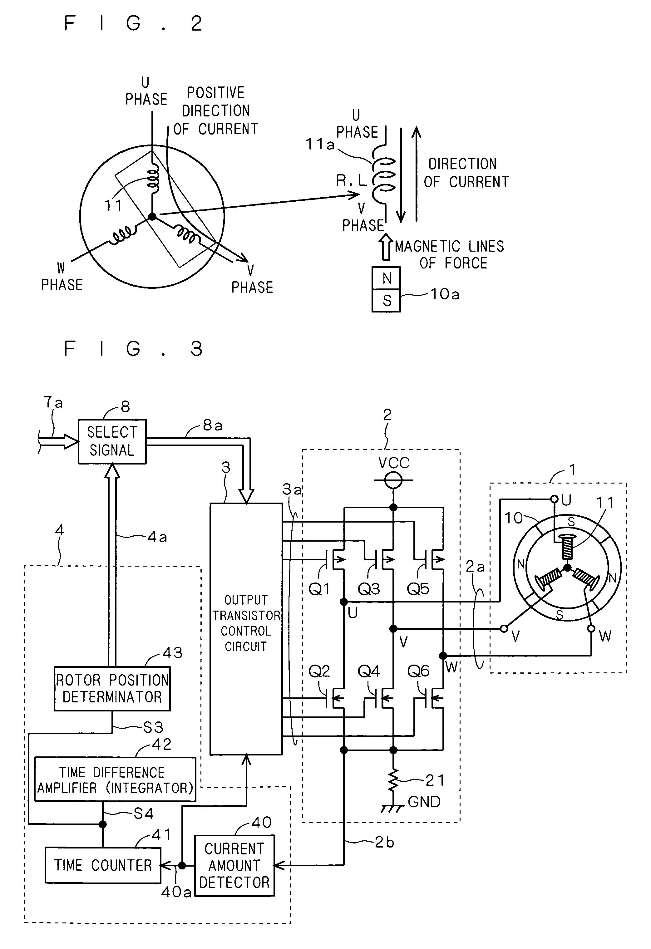
[0038]According to the first embodiment, there are provided a stationary position detection circuit and a motor drive circuit in which an alternating current is supplied to a motor load and the time during which the current flows in a first direction and the time during which the current flows in a second direction opposite to the first direction are converted into electrical signals, which are amplified to determine the position of the motor rotor in stationary mode according to the value of the electrical signals.

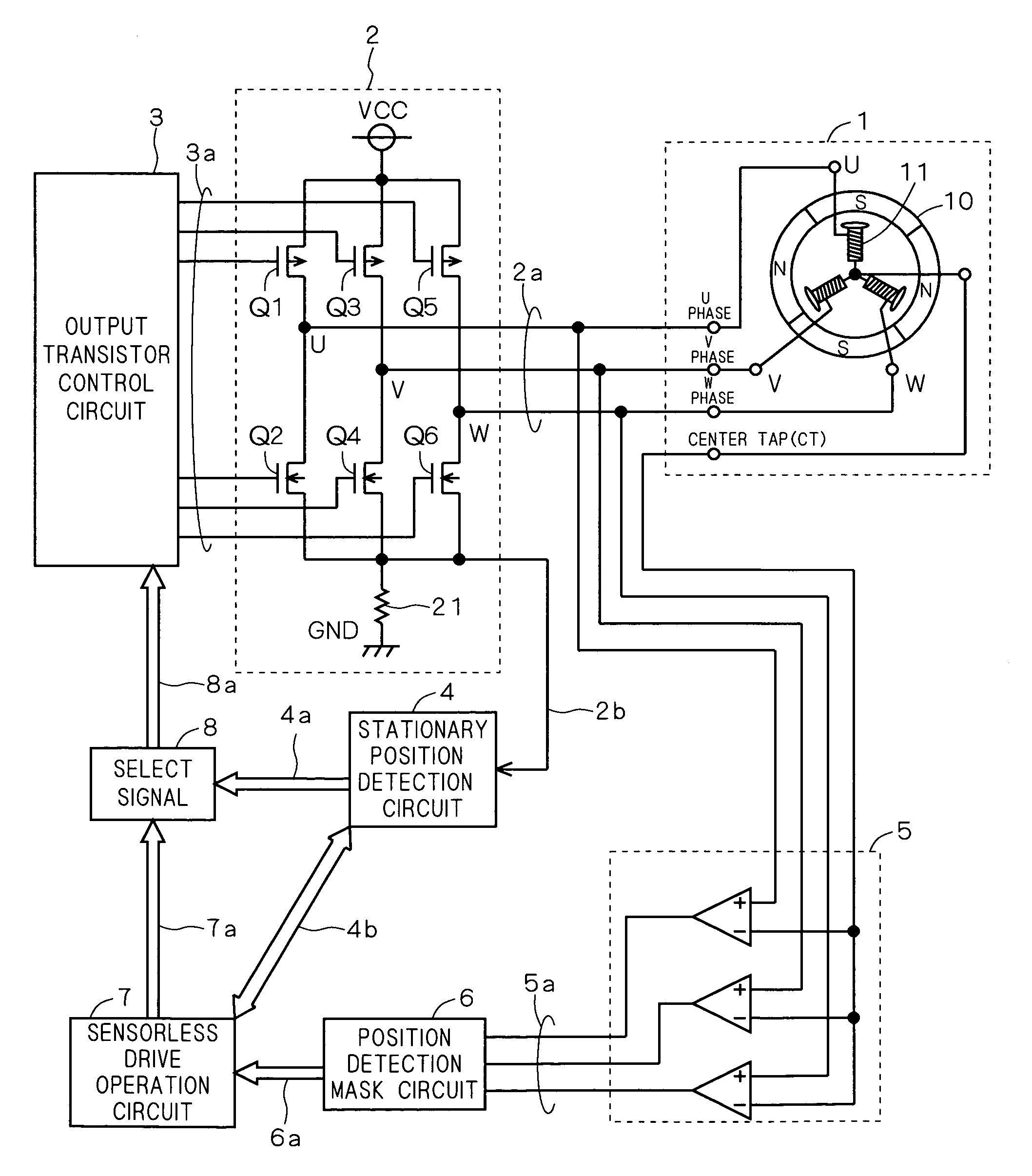
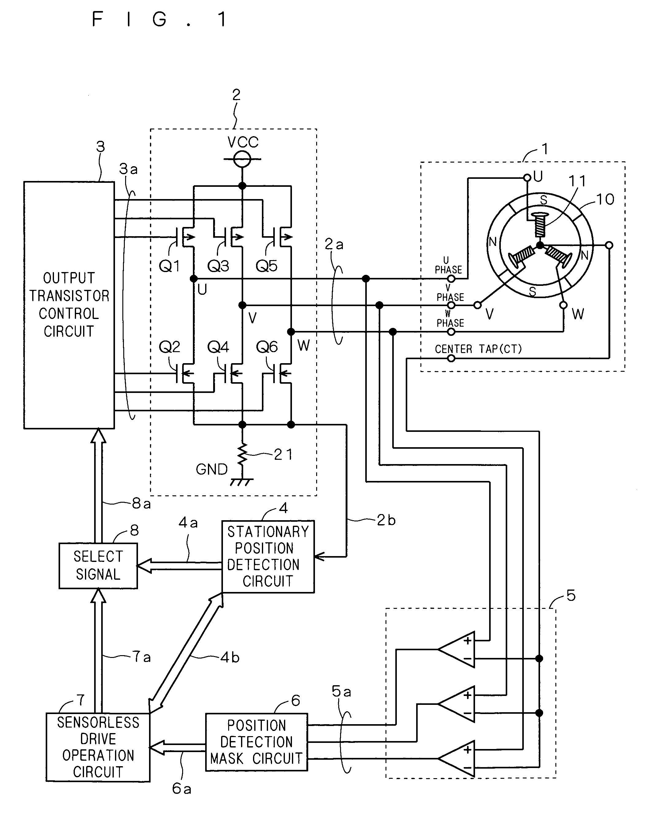
[0039]FIG. 1 is a diagram showing a motor drive circuit and a motor according to this embodiment. As shown in FIG. 1, the motor 1 is, for example, a three-phase DC brushless Hall sensorless motor including a rotor 10 of a permanent magnet and a stator 11 configured of a three-phase load with an armature coil wound on a field core. The load of the stator 11 exists for each of the phases U, V, W and coupled to each other at a center tap (CT).

[0040]The motor drive circuit, o...

second embodiment

[0114]This embodiment is a modification of the stationary position detection circuit and the motor drive circuit according to the first embodiment, and represents another example of the configuration including the time counter 41 and the time difference amplifier 42 according to the first embodiment.

[0115]FIG. 16 is a diagram showing a detailed configuration of the time counter 41a and the time difference amplifier 42a in the stationary position detection circuit 4 according to this embodiment. The time counter 41a includes first and second current sources 410, 413, a first switch 411 for selectively outputting the current I1 from the first current source 410 when the logic value of the detection signal 40a is Low, and a second switch 412 for selectively drawing the current I1 to the second current source 413 when the logic value of the detection signal 40a is Hi. The current output from the first switch 411 and the current drawn by the second switch 412 constitute a current signal ...

third embodiment

[0128]This embodiment is also a modification of the stationary position detection circuit and the motor drive circuit according to the first embodiment, and represents another example of the configuration of the time counter 41 and the time difference amplifier 42 according to the first embodiment.

[0129]FIG. 17 is a diagram showing a detailed configuration of a time counter 41b and a time difference amplifier 42b in the stationary position detection circuit 4 according to this embodiment. The time counter 41b includes a current source 410, a first switch 411 for selectively outputting the current I1 from the current source 410 when the logic value of the detection signal 40a is Low, a second switch 414 for applying a predetermined potential when the logic value of the detection signal 40a is Low, a third switch 415 for selectively outputting the current I1 from the current source 410 when the logic value of the detection signal 40a is Hi, a fourth switch 412 grounded when the logic ...


PUM


Abstract

A stationary position detection circuit and a motor drive circuit capable of more properly detecting the rotor position are disclosed. The stationary position detection circuit supplies an alternating current to each phase load of the motor. The time during which the current flows in a first direction and the time during which the current flows in a second direction opposite to the first direction are converted into electrical signals and amplified. In accordance with the value of the electrical signals, the position of the motor rotor in stationary mode is determined. The use of the alternating current, unlike the kickback voltage, makes it possible to improve the detection accuracy by amplifying the electrical signals with an increased number of alternations. An increased number of alternations can amplify the electrical signals without increasing the value of the alternating current, and therefore, unlike in the case of the kickback voltage, the alternating current of a large value is not required. As a result, the alternating current can be reduced to a small value and the vibration can be suppressed.

Description

BACKGROUND OF THE INVENTION[0001]1. Field of the Invention[0002]The present invention relates to a stationary position detection circuit and a Hall sensorless motor drive circuit capable of detecting the position of a motor rotor.[0003]2. Description of the Background Art[0004]In driving a motor having a rotor such as a small three-phase DC brushless motor, the motor drive circuit is required to be kicked at the time of starting. In the process, unless the rotor position can be detected properly, the proper starting is impossible.[0005]The rotor position can be detected by arranging a Hall sensor configured of a Hall element in the neighborhood of the motor rotor. The use of the Hall sensor, however, leads to an increased cost and a bulkiness. Currently, therefore, vigorous efforts are made to develop what is called a Hall sensorless motor using no Hall sensor.[0006]In the Hall sensorless motor, no induction voltage (counter electromotive voltage) is generated as long as the motor i...

Claims


Application Information

Patent Timeline
Patent Type & Authority Patents(United States)
IPC IPC(8): G01B7/30G05D3/00H02P6/18H02P6/06H02P6/08H02P6/182H02P6/185H02P6/21
CPCG01D5/208H02P3/08H02P6/18
Inventor NARUMI, SATOSHIHOASHI, MASAHARUSUZUKI, TOSHIYASUETSUGU, DAISUKENAKAMURA, HIKARU
Owner RENESAS ELECTRONICS CORP
Why Eureka
Try Eureka