Mass air flow metering device and method

a mass air flow and metering technology, applied in mechanical measuring arrangements, electrical control, instruments, etc., can solve the problems of large output signal, insufficient signal-to-noise ratio, and significant errors in the mass air flow measurement of the engine, so as to reduce the execution time and filter out high frequency noise

Active Publication Date: 2007-02-13
DELPHI TECH IP LTD
View PDF8 Cites 16 Cited by
  • Summary
  • Abstract
  • Description
  • Claims
  • Application Information

AI Technical Summary

Benefits of technology

[0010]The present invention comprises a digital filter requiring minimal execution time and capable of handling pulse frequen...

Problems solved by technology

The inability to determine direction of airflow may result in introduction of significant errors in measure of mass air flow into the engine during conditions wherein reverse flow conditions occur.
However the sensor output signal is extremely small (i.e. range of millivolts) and the corresponding signal-to-noise ratio is not large enough to allow reliable measurement.
Furthermore, it is difficult to manufacture and process the sensor, including placement of the sensors in the middle of the membrane.
Incorrect placement of sensors may result in a drift of the ...

Method used


Image

  • Mass air flow metering device and method
  • Mass air flow metering device and method
  • Mass air flow metering device and method

Examples


Embodiment Construction

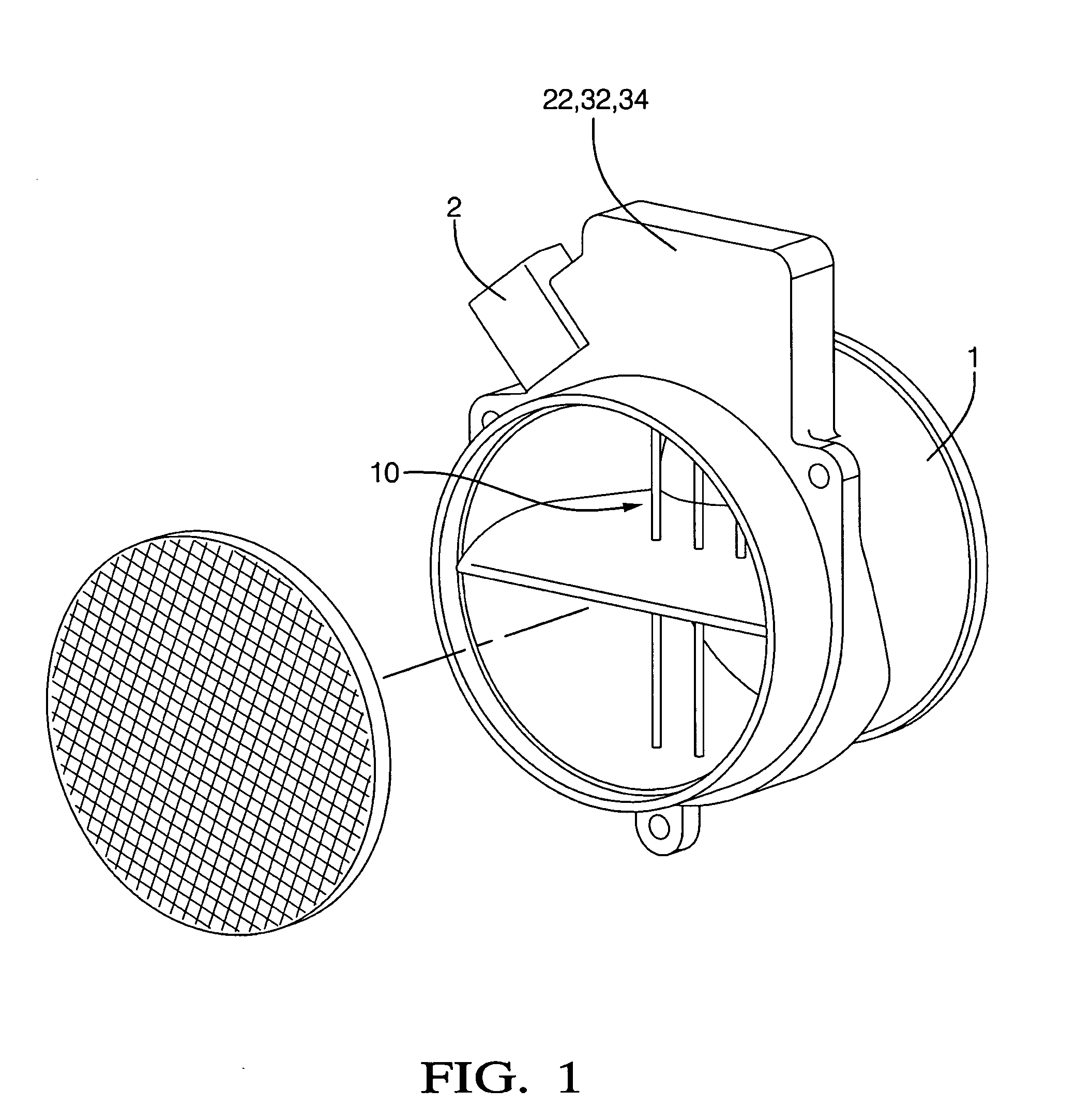
[0023]Referring now to the drawings, wherein the showings are for the purpose of illustrating the invention only and not for the purpose of limiting the same, FIG. 1 shows a mass airflow meter 1 which has been constructed in accordance with an embodiment of the present invention.

[0024]The mass airflow sensor 1 of this embodiment preferably comprises a conventional unidirectional sensor, and is an element of an air intake system, preferably located in an air flowstream between an air filter and an intake manifold of an internal combustion engine (not shown). The air intake system includes ducting leading from the air filter to the intake manifold, and is designed to ensure all air entering the intake manifold passes through the air filter and past the mass air flow sensor. The air intake system is typically located in an engine compartment when included on a vehicle. The exemplary mass airflow meter 1 comprises a conventional hot-film anemometric sensing device 10 operable to sense m...


PUM


Abstract

An airflow metering device, including a conventional airflow sensing device signally connected to a signal processor is shown, having an input flow signal correlatable to a magnitude of mass air flowing past the airflow sensing device. The signal processor is operable to determine a flow correction factor based upon a direction and magnitude of the mass air flowing past the airflow sensing device. The output of the airflow metering device is an accurate measure of airflow, and comprises the input flow signal of the airflow sensing device adjusted by the flow correction factor determined by the signal processor.

Description

TECHNICAL FIELD[0001]This invention pertains generally to internal combustion engine control systems, and more specifically to a method and apparatus to accurately meter flow of air into the internal combustion engine.BACKGROUND OF THE INVENTION[0002]A typical air meter for measuring air intake into an internal combustion engine operates on the principle of hot-film anemometry. A heated element is placed within the airflow stream, and maintained at a constant temperature differential above the air temperature. The amount of electrical power required to maintain the heated element at the proper temperature is a direct function of the mass flow rate of the air past the element.[0003]The measurement function of the typical mass air flow meter is performed using a bridge circuit, often referred to as a Wheatstone bridge, and shown as element 10 in FIG. 2. In this circuit, temperature-sensitive resistors are used as the ambient temperature sensor A1 and as the heated sensing element H1. ...

Claims


Application Information

Patent Timeline
IPC IPC(8): G06F19/00
CPCF02D41/187G01F1/72G01F1/68F02D2041/2072F02D2041/285
Inventor HOCKEN, LARY ROBERTGEE, GREGORY PAULPRAWDZIK, DAVID PAULDU BOIS, PAUL LOUISSMITH, JAMES CRAIG
Owner DELPHI TECH IP LTD
Why Eureka
Try Eureka