Thermal control system and method

a control system and control system technology, applied in the field of thermal control system and method, can solve the problems of limited input pressure of the compressor, and achieve the effects of high thermal efficiency, high speed response, and rapid adjustmen

Active Publication Date: 2007-02-20
BE AEROSPACE INCORPORATED
View PDF6 Cites 96 Cited by
  • Summary
  • Abstract
  • Description
  • Claims
  • Application Information

AI Technical Summary

Benefits of technology

[0009]Systems and methods in accordance with the invention employ a variable phase refrigerant directly as a cooling or heating source throughout a wide temperature range and with high speed response and high thermal efficiency. The refrigerant is maintained as a saturated mix of liquid and vapor during the principal part of its thermal control range and in direct contact with a controlled unit functioning as a variable heat load. The temperature of controlled equipment can be adjusted very rapidly by variation of the pressure of the saturated fluid mix. The energy losses in conduits, HEXs and fluid masses are minimized and the delay in temperature response of the cooled device due to the change in temperature of these components is substantially eliminated.
[0010]Systems and methods in accordance with the invention, in more specific examples, compress a cycling refrigerant to a high temperature, high pressure state, but provide proportional control of a hot gas flow, as well as a separate flow of a condensed liquid / vapor mist. The liquid / vapor mist initially comprises an expanded flow of condensed refrigerant, but is combined with a proportioned flow of hot gas, determined by a controller, in accordance with a chosen set point for the controlled device. To this end the two flows are brought together in a mixing circuit, at which the saturated fluid is brought to a target temperature and pressure and a pressure drop is introduced in the expanded flow to compensate for flow nonlinearities inherent in the expansion valve device. The saturated fluid itself is then transported directly through the controlled process or equipment. The temperature of the controlled process or equipment is sensed and sent to the controller, which can vary the temperature of the controlled system rapidly simply by pressure change. By thus changing the temperature of the medium effecting the cooling or heating, such change in temperature can be made available to the controlled device nearly immediately following the pressure change. This eliminates many thermal energy losses and temperature changes arising from use of a separate thermal transfer fluid in contrast with the controlled device.
[0011]The invention herein disclosed thus effectively can apply cooling or heating to a controlled device rapidly enough so as to counteract the effects of a change in power applied to the controlled device and thereby keep the controlled device at an invariant temperature.
[0012]In moving the refrigerant through a complete continuous cycle for ultimate direct heat transfer, a number of novel expedients are utilized to assure that the phases of the refrigerant are stable throughout. At the compression step, for example, a balance of input temperature and pressure is maintained at the compressor by employing a desuperheater valve responsive to the compressor input temperature, and a feed-through loop with an electrical heater and heat exchange system is incorporated so as to assure that the input flow at the compressor input is raised to the proper range if necessary. This balance also assures that refrigerant returned to the compressor input is free of liquid as well as in a selected pressure range. In addition, input pressure to the compressor is limited by a close-on-rise valve in the return flow path from the controlled process.

Problems solved by technology

In addition, input pressure to the compressor is limited by a close-on-rise valve in the return flow path from the controlled process.

Method used


Image

  • Thermal control system and method
  • Thermal control system and method
  • Thermal control system and method

Examples


Embodiment Construction

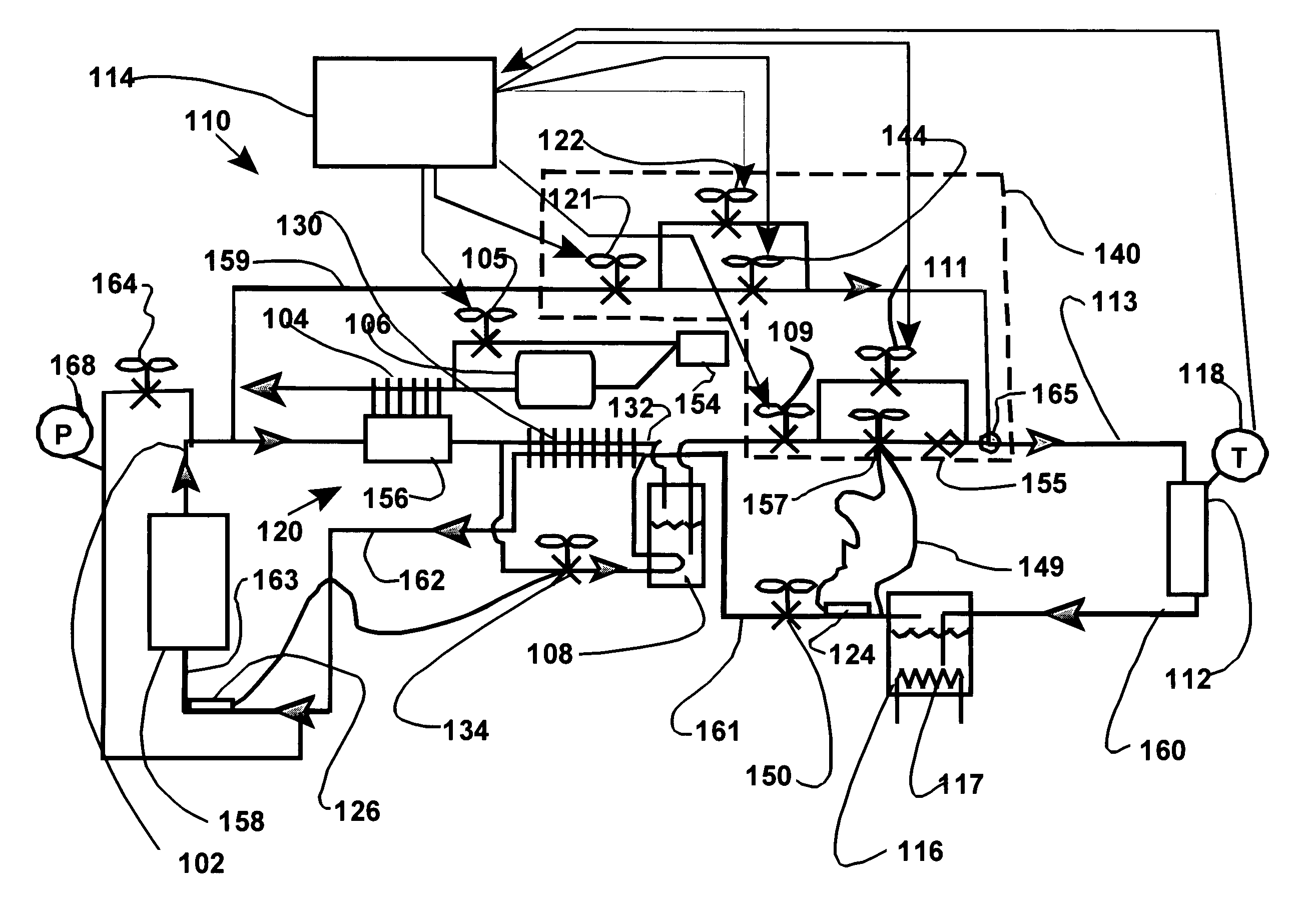
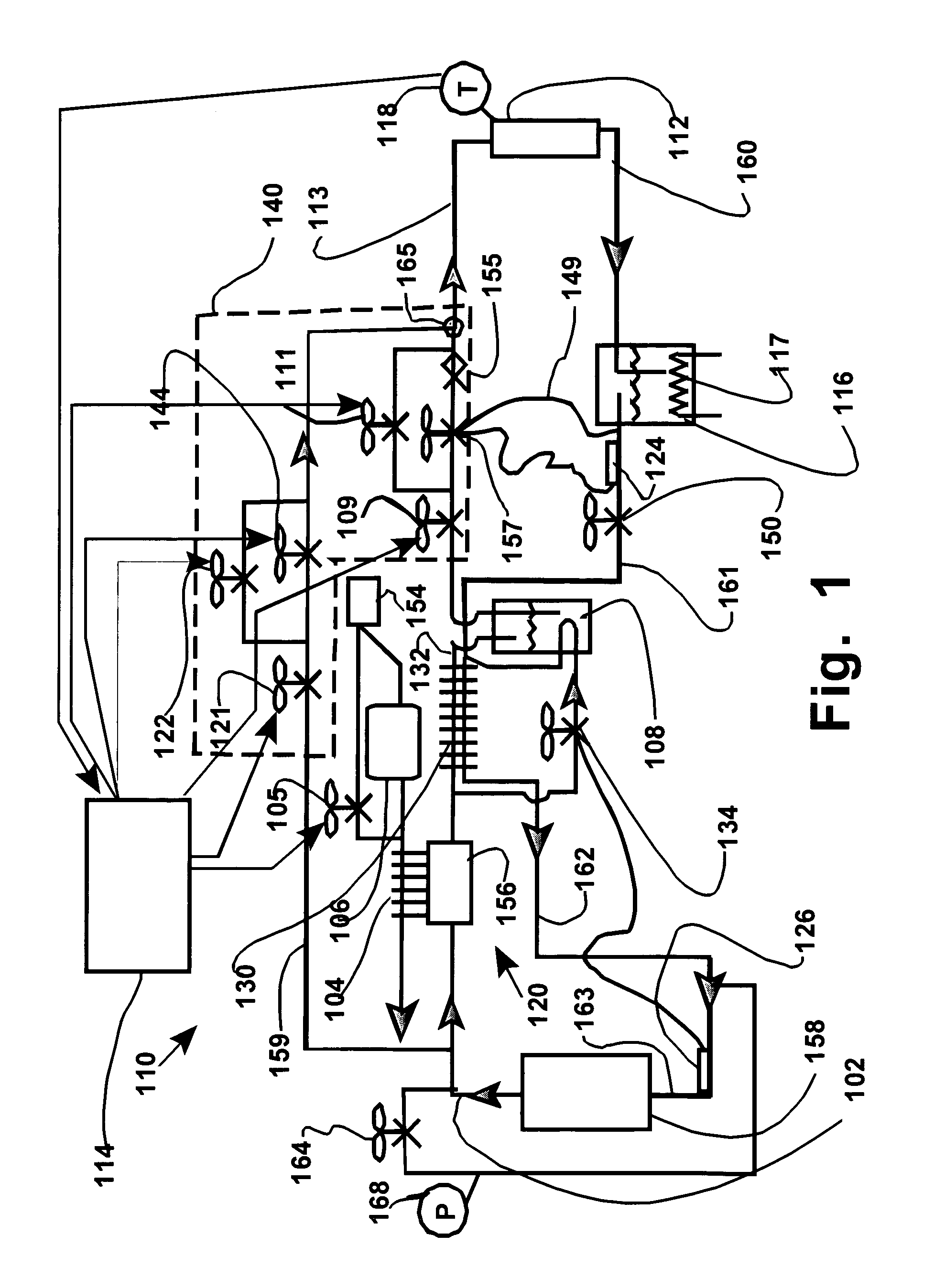
[0025]A block diagram of a temperature control unit (TCU) 110 is depicted in FIG. 1 for operation principally in the range of approximately −50° C. to +140° C., by way of example only. Other temperature ranges may be utilized, depending upon the refrigerant and to some extent the load, but the example given assumes the use of refrigerant R507 as an example. TCU 110 can be a compact unit and is characterized by low cost as well as moderate size, enhanced economy and rapid response. Temperature levels are to be held stable at different target levels irrespective of the lengths of the lines coupling associated devices. The TCU 110 in this example is intended for the purpose of controlling the temperature of a tool 112, such as a cluster tool for semiconductor fabrication. Such tools have internal passageways for passage of a thermal control fluid. The TCU is intended to establish different target temperatures of the tool for operating cycles during different fabrication steps.

[0026]The...


PUM


Abstract

A system and method for controlling the temperature of a process tool uses the vaporizable characteristic of a refrigerant that is provided in direct heat exchange relation with the process tool. Pressurized refrigerant is provided as both condensed liquid and in gaseous state. The condensed liquid is expanded to a vaporous mix, and the gaseous refrigerant is added to reach a target temperature determined by its pressure. Temperature corrections can thus be made very rapidly by gas pressure adjustments. The process tool and the operating parameters will usually require that the returning refrigerant be conditioned and processed for compatibility with the compressor and other units, so that cycling can be continuous regardless of thermal demands and changes.

Description

REFERENCE TO PRIOR APPLICATIONS[0001]This invention relies for priority on Provisional Patent Application No. 60 / 546,059 filed Feb. 19, 2004, entitled “Transfer Direct of Saturated Fluid System”, and Provisional Application No. 60 / 576,705 filed Jun. 2, 2004, entitled “Transfer Direct Heat Exchanger System”, both naming Kenneth W. Cowans, Glenn Zubillaga and William W. Cowans as inventors.BACKGROUND OF THE INVENTION[0002]Thermal control units (TCUs), such as heating and chilling systems are widely used to establish and maintain a process tool or other device at a selected and variable temperature. Typical examples of a modem thermal or temperature control unit are found in highly capital intensive semiconductor fabrication facilities. Stringent spatial requirements are placed on the TCUs, in order to preserve expensive floor space as much as possible. Reliability must be assured, because the large capital equipment costs required do not tolerate downtime in operation if profitable pe...

Claims


Application Information

Patent Timeline
Patent Type & Authority Patents(United States)
IPC IPC(8): F25B41/00F25B1/00F25B49/00F25B15/00F25B30/02F25B40/00F25B41/04F25B49/02
CPCF25B41/00F25B41/04F25B30/02F25B2700/2117F25B49/027F25B2339/047F25B2400/0403F25B2400/0411F25B2400/0415F25B2400/13F25B2400/16F25B2600/0261F25B2600/2501F25B2700/21151F25B40/00Y02A40/963F25B41/20F25B49/00F25B15/00
Inventor COWANS, KENNETH W.COWANS, WILLIAM W.ZUBILLAGA, GLENN W.MILLAN, ISAAC
Owner BE AEROSPACE INCORPORATED
Why Eureka
Try Eureka