High temperature centerbody for temperature reduction by optical reflection and process for manufacturing

a technology of optical reflection and manufacturing process, applied in the field of gas turbine engines, can solve the problems of insufficient tbcs, prone to failure of advanced cycle turbine engines, and low efficiency of high-efficiency centerbodies, so as to reduce the mean time between repair or refurbishment, prolong the component life, and increase the engine efficiency

Inactive Publication Date: 2007-02-27
GENERAL ELECTRIC CO
View PDF23 Cites 10 Cited by
  • Summary
  • Abstract
  • Description
  • Claims
  • Application Information

AI Technical Summary

Benefits of technology

[0011]An advantage of the present invention is that the radiation from the combustion process is reflected back into the gas flow path. This radiative heat, rather than being absorbed by a component in the combustor, HPT, LPT, or primary exhaust nozzle portion of the engine, is absorbed by the fluid and carried back into portions of the engine further aft that currently operate at cooler temperatures or out into the atmosphere. The result is that the component does not become as hot. At a given temperature of operation of the engine, the component, because it is operating at a cooler temperature, will not deteriorate as rapidly due to thermal degradation, resulting in longer component life and less mean time between repair or refurbishment. Another advantage of the present invention is that the fluid stream will be heated to a higher temperature as the reflected radiation is absorbed by the materials comprising the gaseous fluid and carried from the combustor portion of the engine into the aft turbine portions of the engine. This increased fluid temperature translates into increased engine efficiency, as the available energy in the fluid stream for both extraction by the turbine to operate the engine and for thrust to propel the aircraft is greater. Still another advantage of the present invention is that the engine can be operated at an even higher temperature than currently experienced using the current invention if shortened component life and increased repair rates can be tolerated in exchange for even greater efficiency.

Problems solved by technology

However, as temperatures of combustion have increased, even these TBCs have been found to be insufficient.
In particular, the centerbodies of high efficiency, advanced cycle turbine engines are prone to failure as a result of thermal degradation.

Method used


Image

  • High temperature centerbody for temperature reduction by optical reflection and process for manufacturing
  • High temperature centerbody for temperature reduction by optical reflection and process for manufacturing
  • High temperature centerbody for temperature reduction by optical reflection and process for manufacturing

Examples


Embodiment Construction

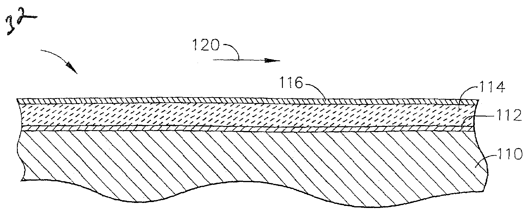
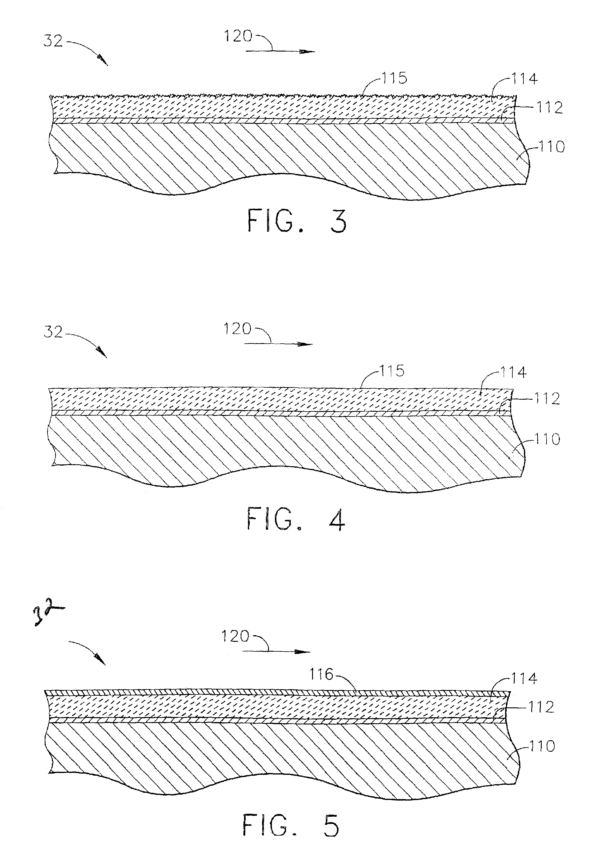
[0018]In accordance with the present invention, hot section components of a gas turbine engine which form the boundary of the gas flow path or which are located in the gas flow path are coated with a thin layer of a specular optical reflective material that has a high temperature capability. The material as applied has a smooth surface finish so as to speculary reflect the heat back into the fluid path and away from other hot section components.

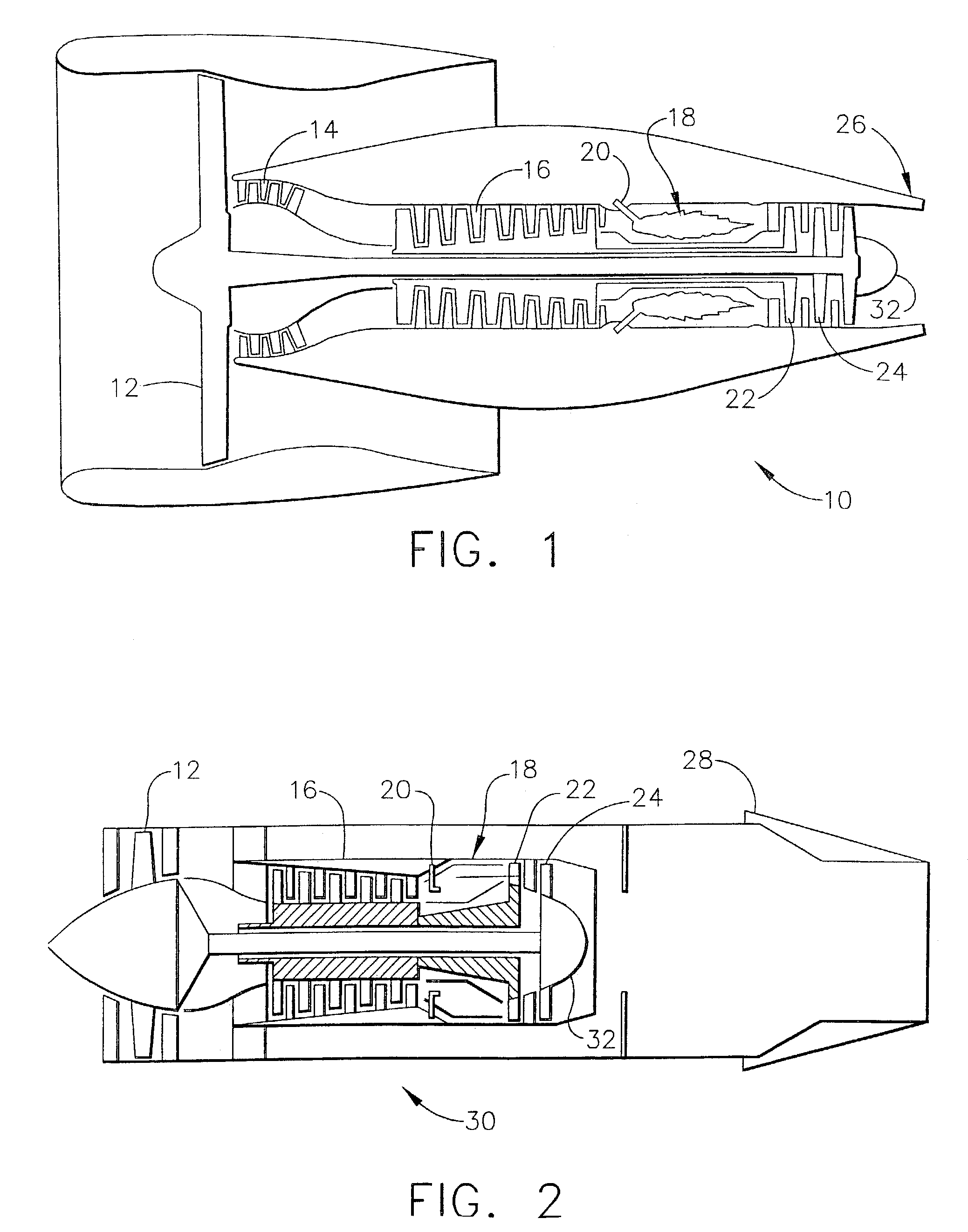
[0019]A high bypass aircraft gas turbine engine 10 is shown schematically in FIG. 1. During operation, air is forced through the fan 12. A portion of the air bypasses the core of the engine and is used to contribute to the thrust that propels the engine. A portion of the air is compressed in the booster 14 and compressor 16 portions of the engine up to 10–25 times atmospheric pressure, and adiabatically heated to 800° F.–1250° F. (430° C.–680° C.) in the process. This heated and compressed air is directed into the combustor portion of the eng...


PUM

PropertyMeasurementUnit
thicknessaaaaaaaaaa
temperaturesaaaaaaaaaa
temperatureaaaaaaaaaa

Abstract

A high temperature gas turbine component for use in the gas flow path that also is a specular optical reflector. A thin layer of a high temperature reflector is applied to the gas flow path of the component, that is, the surface of the component that forms a boundary for hot combustion gases. The component typically includes a thermal barrier coating overlying the high temperature metallic component that permits the component to operate at elevated temperatures. The thermal barrier coating must be polished in order to provide a surface that can suitably reflect the radiation into the gas flow path. A thin layer of the high temperature reflector the is applied over the polished thermal barrier coating by a process that can adequately adhere the reflector to the polished surface without increasing the roughness of the surface. The high temperature reflector can be applied to any surface aft of the compressor, such as on a centerbody. The surface reflects radiation back into the hot gas flow path or into the atmosphere. The reflected radiation is not focused onto any other hardware component. The design of the component is such that the radiation is returned to the gas flow path or sent to the atmosphere rather than absorbed into a component wall that only serves to increase the temperature of the wall.

Description

CROSS-REFERENCE TO RELATED APPLICATIONS[0001]This Application is related to application Ser. No. 10 / 335,657, filed contemporaneously with this Application on Dec. 31, 2002, entitled “IMPROVED HIGH TEMPERATURE SPLASH PLATE FOR TEMPERATURE REDUCTION BY OPTICAL REFLECTION AND PROCESS FOR MANUFACTURING” assigned to the assignee of the present invention and which is incorporated herein by reference, to application Ser. No. 10 / 335,486, filed contemporaneously with this Application on Dec. 31, 2002, entitled “IMPROVED HIGH TEMPERATURE TURBINE NOZZLE FOR TEMPERATURE REDUCTION BY OPTICAL REFLECTION AND PROCESS FOR MANUFACTURING” assigned to the assignee of the present invention and which is incorporated herein by reference, and to application Ser. No. 10 / 335,442, filed contemporaneously with this Application on Dec. 31, 2002, entitled “IMPROVED HIGH TEMPERATURE COMBUSTOR WALL FOR TEMPERATURE REDUCTION BY OPTICAL REFLECTION AND PROCESS FOR MANUFACTURING” assigned to the assignee of the presen...

Claims


Application Information

Patent Timeline
Patent Type & Authority Patents(United States)
IPC IPC(8): F02K1/78B32B15/04F01D25/00C23C30/00F01D5/28F02C7/00
CPCF01D5/288F23M2900/05004Y02T50/67Y02T50/672Y02T50/673F05D2300/133F05D2230/90F05D2300/143F05D2300/611F05D2300/211F05D2300/504F23R3/002Y02T50/60
Inventor ACKERMANN, JOHN FREDERICKARSZMAN, PAUL V.NAGARAJ, BANGALORE A.YOUNG, CRAIG D.JUSTIS, NICOLE
Owner GENERAL ELECTRIC CO
Why Eureka
Try Eureka