Autonomous robotic crawler for in-pipe inspection

a robotic crawler and crawler technology, applied in the field of robotic equipment, can solve the problems of small air cylinders that do not have the capacity to generate enough pushing force directly against miniature air cylinders, and few advances in the design of crawling apparatuses having adequate motive forces

Inactive Publication Date: 2007-02-27
RICE UNIV +1
View PDF29 Cites 107 Cited by
  • Summary
  • Abstract
  • Description
  • Claims
  • Application Information

AI Technical Summary

Benefits of technology

[0014]In a preferred embodiment of the present invention, a robot for in-pipe inspection includes a drive module having a plurality of wheels inclined at an angle greater than zero degrees and less than ninety degrees to the longitudinal axis of the pipe, a driver module having a plurality of wheels aligned parallel to the longitudinal axis of the pipe, and a power source. The driver module is preferably connected to the drive module such that the drive and driver modules cooperate to move the robot through the pipe or conduit. Various sources of power can be used with the present device. Particularly preferred is a turbine system that allows the device to be powered by the a flow of fluid, such as air, through the pipe or conduit.

Problems solved by technology

While current advances in miniaturization technology have made cameras and sensors small enough to fit within a small diameter pipe, there have been few advances in the design of a crawling apparatus having adequate motive forces to deploy a small diameter inspection apparatus through an extensive pipe system.
For example, miniature electric motors do not provide enough motive force to pull extensive length tethers behind the crawler.
Similarly, miniature air cylinders do not have the capacity to generate enough pushing force directly against the inner-walled pipe as is required for inch-worm motion.
In addition, neither technology is capable of propelling an inspection devices of the mile-plus distances that may be required.
While suitable for use in large diameter pipelines and traveling short distances, the crawler of Sullins et al. would not be feasible for use in coiled tubing for the following reasons.
First, Sullins et al's crawler includes x-ray equipment (e.g. x-ray tube), which has not yet been fabricated to fit in small pipe diameters.
Secondly, because x-ray equipment requires a large amount of power to operate, the size of the power source is dependent on the x-ray equipment, and thus greatly increased.
Therefore, in addition to the x-ray equipment, the size of the power source may prohibit the crawler from traveling in small diameter spaces for long distances.
However, there are limitations to the size and motive force capable of being exerted by these prior art devices as set forth above.

Method used


Image

  • Autonomous robotic crawler for in-pipe inspection
  • Autonomous robotic crawler for in-pipe inspection
  • Autonomous robotic crawler for in-pipe inspection

Examples


Embodiment Construction

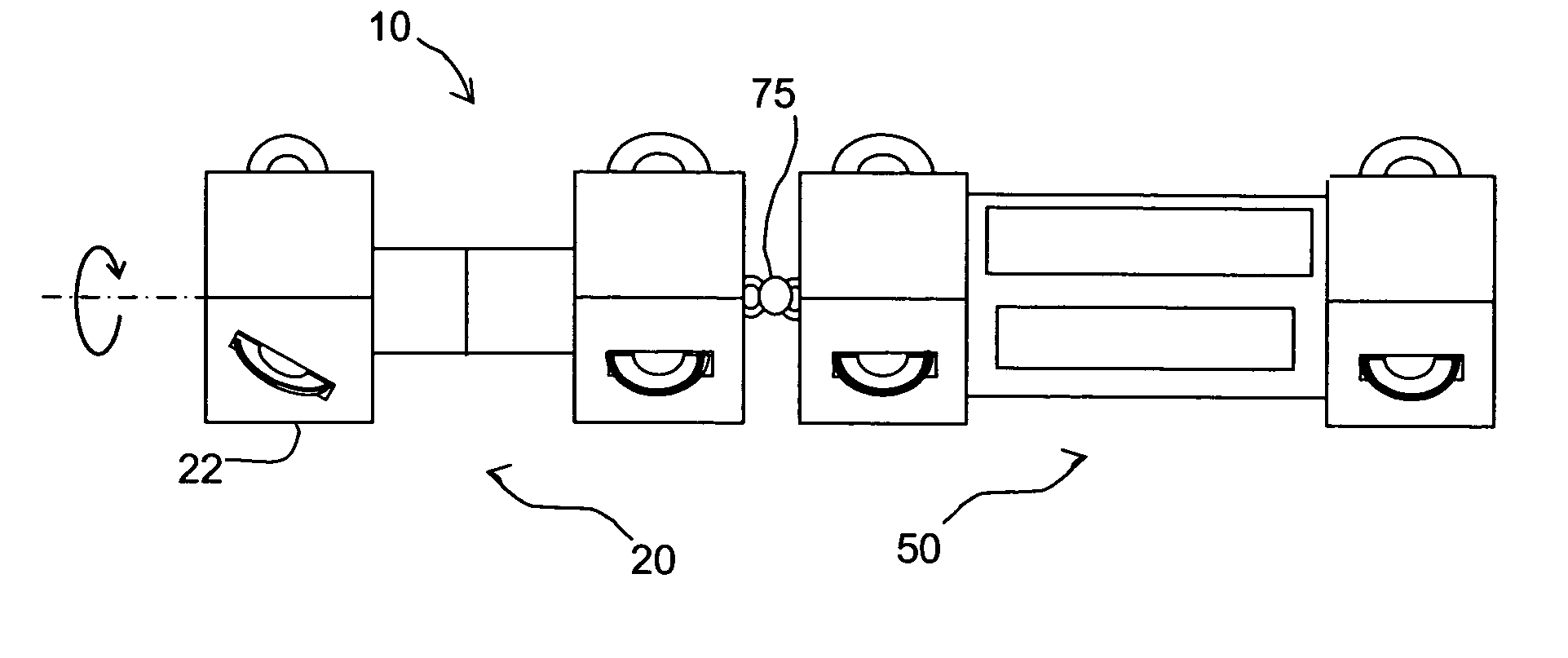
[0028]In order to fully describe the embodiments of the present invention, reference will be made throughout this description to a longitudinal axis. The longitudinal axis is parallel to the axis of symmetry of the conduit or pipe through which the robot is traveling. It should be appreciated that the scope of the invention is only limited by the claims and not by this description.

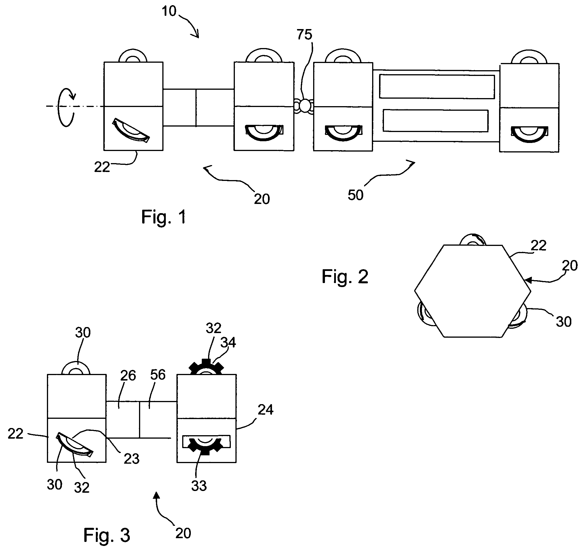
[0029]Referring initially to FIGS. 1 and 2, the present invention provides a pipe-crawling robot 10. Robot 10 generally consists of at least two independently modular, articulated segments: first segment 20 and second segment 50. First segment 20 is preferably connected to second segment 50 by a flexible coupling 75. Flexible coupling 75 is free to bend about the longitudinal axis of robot 10, but prevents the relative rotation about the longitudinal axis. The combination of first segment 20 and second segment 50 provide the locomotive motion of robot 10, as will be described below in detail.

[0030]Referrin...


PUM


Abstract

The specification discloses a robot for inspection adapted to travel virtually unlimited distances through small-diameter enclosed spaces such as conduits or ducts, preferably using a fluid-driven screw-drive propulsion system. The robot preferably includes a plurality of wheels inclined at an angle greater than zero degrees and less than ninety degrees to the longitudinal axis of the pipe, a plurality of wheels aligned parallel to the longitudinal axis of the pipe, and a power system for causing relative rotation of the sections bearing the pitched and non-pitched wheels. The robot may include internal fluid flow passages, notched wheels, multiple retractable wheels, and is configured so as to have an operating diameter less than six and preferably less than two inches.

Description

CROSS-REFERENCE TO RELATED APPLICATIONS[0001]This application is a continuation-in-part of U.S. patent application Ser. No. 10 / 272,846, filed Oct. 17, 2002, which claims the benefit of U.S. provisional patent application Ser. No. 60 / 329,862, filed Oct. 17, 2001, both of which are incorporated herein by reference in their entireties.STATEMENT REGUARDING FEDERALLY SPONSORED RESEARCH OR DEVELOPMENT[0002]Not Applicable.BACKGROUND OF THE INVENTION[0003]1. Field of the Invention[0004]The present invention generally relates to a robotic apparatus and, more particularly, to a robotic apparatus adapted to travel through enclosed spaces such as conduits or ducts using mechanically enabled helical-like motions.[0005]2. Background of Relevant Art[0006]Pipe crawlers, pipe inspection pigs and similar vehicles are widely used for inspecting the interior surfaces of piping systems, storage tanks, and process vessels for damaged or flawed structural features. Typically, such devices include a testin...

Claims


Application Information

Patent Timeline
Patent Type & Authority Patents(United States)
IPC IPC(8): B61F13/00G01M99/00F16L55/26F16L55/32F16L55/36F16L55/38F16L55/48
CPCF16L55/26F16L55/265F16L55/36F16L55/38F16L55/32F16L2101/30
Inventor GHORBEL, FATHI HASSANDABNEY, JAMES BRUSTER
Owner RICE UNIV
Why Eureka
Try Eureka