Electrochemical sensing circuit having high dynamic range

a sensing circuit and high-dynamic range technology, applied in the field of electrochemical sensing circuits, can solve the problems of high frequency oscillation, negative counter electrode charge, prone to oscillation, etc., and achieve the effects of high dynamic range, high sensitivity, and rapid sensor recovery

Inactive Publication Date: 2007-02-27
MAPLE CHASE
View PDF2 Cites 4 Cited by
  • Summary
  • Abstract
  • Description
  • Claims
  • Application Information

AI Technical Summary

Benefits of technology

[0011]In view of the above, it is an object of the present invention to provide a new and improved electronic circuit that senses cell current flow from a three terminal electrochemical gas sensor cell that overcomes the above problems existing in the art. More particularly, it is an object of the present invention to provide a new and improved amplifier configuration that allows high sensitivity to the electrochemical gas sensor cell output during periods of low gas concentration while allowing for rapid sensor recovery when the electrochemical gas sensor is exposed to very high gas concentrations. Specifically, it is an object of the present invention to provide a new and improved electronic circuit for sensing the output of a electrochemical gas sensor that has a very high dynamic range such that operation of the hazardous condition detector in which it is utilized may meet agency standards.
[0012]In the electronic circuit of one embodiment to the present invention the circuitry provides high resolution of measurements while limiting the power supply needed for high concentrations of gas. In this embodiment, this is achieved by utilizing a non-linear element in the feedback of an amplifier. As such, at low levels of gas concentration the output signal is defined by the feedback resistance. At the point that the non-linear element begins to conduct, the gas concentration is high and the area of interest for linear signals has passed. Under such conditions the amplifier circuitry is still able to maintain the current sourced by the electrochemical gas sensor with a much smaller power supply.
[0013]In a preferred embodiment of the present invention, the electronic sensing circuitry utilizes a resistive feedback from the output of an amplifier to the working electrode of a three terminal electrochemical gas sensor cell. In addition to this feedback resistor, a pair of series connected transistors are coupled in parallel to the feedback resistor. These two transistors act as a single diode in that they do not conduct in negative polarity. However, in positive polarity there exists a region of potential in which no current will flow through these devices, i.e., the feedback resistor is the only element through which current may flow. If the voltage potential increases beyond the turn on voltage of the transistors, they will begin to conduct current. This conduction will allow the amplifier to maintain the current through the electrochemical sensor without requiring additional voltage potential across the feedback resistor. This provides an increased dynamic range of the amplifier while still utilizing the low voltage supply of the battery.

Problems solved by technology

A disadvantage of this prior known circuit shown in FIG. 1 is that it is prone to oscillation because the virtual earth impedance of each amplifier appears as part of a feedback path of the other amplifier.
This can lead to oscillation at high frequencies where the virtual earth impedances are not well defined.
A further disadvantage is that, whereas Vout is normally positive when gas is being sensed, the counter electrode charges negatively, requiring the output of amplifier A1 to go negative.
Instead, because many such carbon monoxide detectors are battery powered devices, the number and magnitude of the power supply voltages powering the electronics is the limiting factor.
With such a limitation, the problem is to allow the amplifier, e.g., a transimpedance amplifier (TIA) to convert the sensor output current for low level exposures to CO to be read by the microprocessor, and still allow the amplifier to have enough capacity such that it can source the current produced by the electrochemical cell at the tens of thousands of ppm exposure to CO gas for over exposure conditions.
If the sensing electronics are unable to source this higher current, the sensor typically becomes biased and is unable to recover quickly from such high concentration exposures.

Method used


Image

  • Electrochemical sensing circuit having high dynamic range
  • Electrochemical sensing circuit having high dynamic range
  • Electrochemical sensing circuit having high dynamic range

Examples


Embodiment Construction

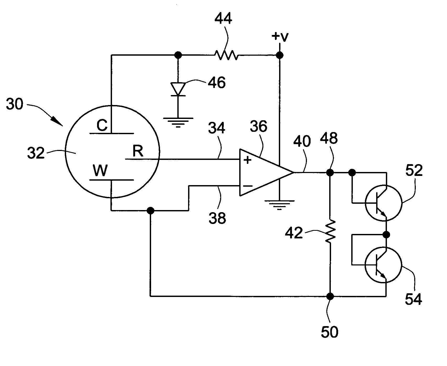
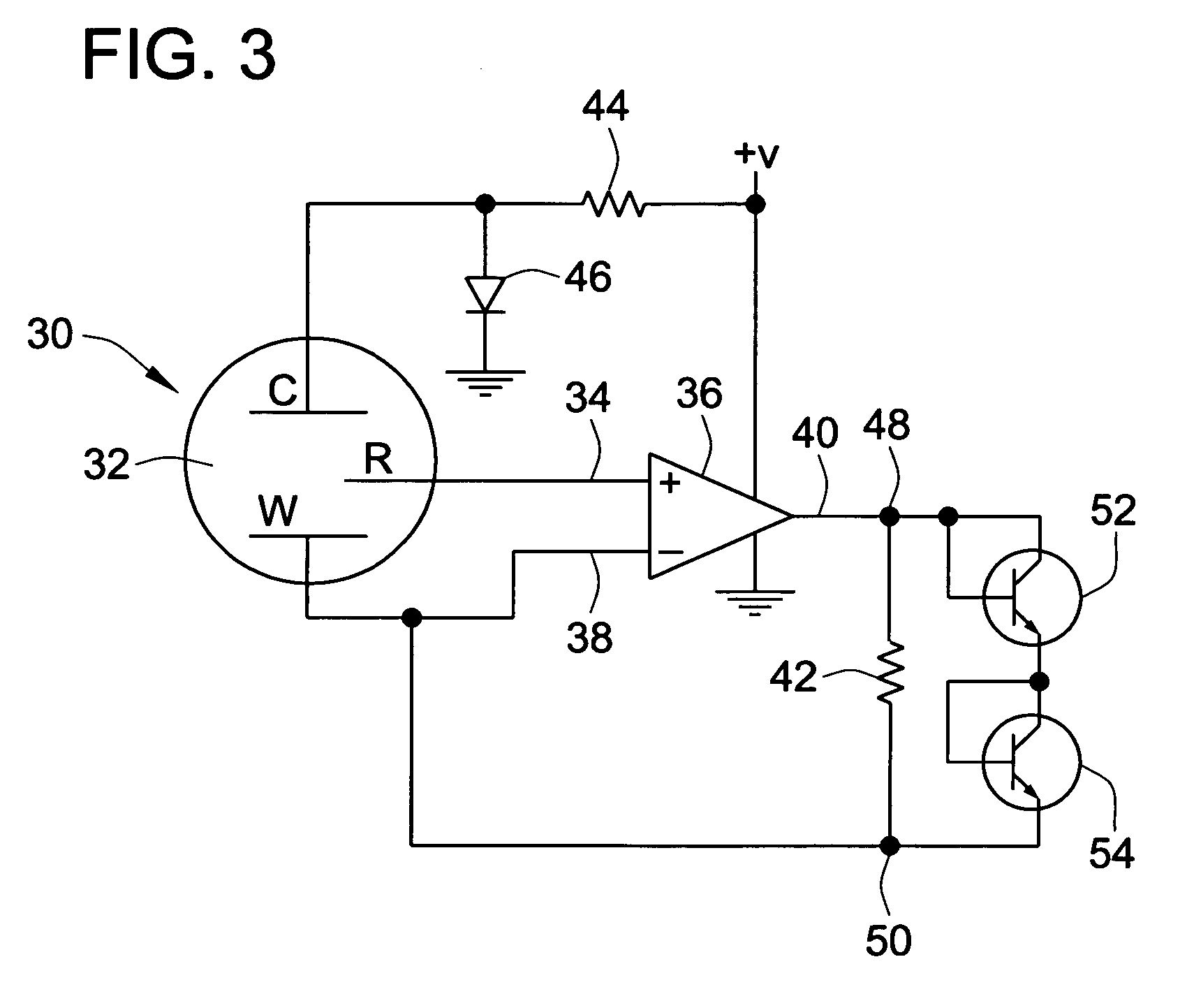
[0020]Referring to FIG. 3, the electrochemical cell 30 is of conventional construction and comprises a chamber, or cavity 32 into which a gas to be monitored is introduced. Three spaced electrodes W, C, R are located in the cavity 32. Electrode R constitutes a reference electrode and is connected to an input 34 of an operational amplifier 36. A second input 38 of amplifier 36 is connected to the electrode W. The output 40 of the amplifier 36 is connected to electrode W through a feedback loop which includes resistor 42. The counter electrode, C, is connected to a reference voltage generated by resistor 44 and diode 46 which is connected to the circuit ground.

[0021]The amplifier 36 feeds back current through resistor 42 to maintain the working and reference electrodes, W and R respectively, at the same potential.

[0022]When gas is sensed by the cell 30, the output of amplifier 36 goes positive to deliver a positive current into the working electrode W, and at the same time, the electr...


PUM

PropertyMeasurementUnit
polarityaaaaaaaaaa
voltageaaaaaaaaaa
concentrationaaaaaaaaaa

Abstract

An electronic sensing circuit for an electrochemical gas sensor cell providing high dynamic range is described. The electronic circuit utilizes an amplifier with a resistive feedback element to provide high sensitivity linear sensing of low detected gas concentrations. The electronic circuit also provides the ability to source sufficient current to prevent the electrochemical gas sensor cell from becoming biased under very high gas concentration conditions. This operation is enabled by adding a non-linear element in the feedback path of the amplifier, which non-linear element begins to conduct during the high gas concentration conditions.

Description

FIELD OF THE INVENTION[0001]The present invention relates generally to electrochemical sensing circuits and more particularly to electrical circuits which sense cell current flow from a three terminal electrochemical cell.BACKGROUND OF THE INVENTION[0002]Three terminal electrochemical cells are used for a variety of gas monitors. These monitors comprise a cell in which a gas to be analyzed is introduced and three spaced apart electrodes. The three electrodes comprise a main pair across which the cell current is generated and a reference electrode which enables a potential at a predetermined point in the cell electrolyte measured. The cell current is proportional to the concentration of the compound or element being sensed by the cell, which may, for example, be carbon monoxide.[0003]Known three-terminal electrochemical cells can be stabilized using the circuit shown in FIG. 1. In order to stabilize the cell, the “working” and “reference” electrodes, labeled “W” and “R” respectively ...

Claims


Application Information

Patent Timeline
Patent Type & Authority Patents(United States)
IPC IPC(8): G01N27/416
CPCG01N27/4045G01N27/26G01N27/416G01N27/403
Inventor KAISER, TIMOTHY D.
Owner MAPLE CHASE
Why Eureka
Try Eureka