Method for manufacturing color filter

a color filter and manufacturing method technology, applied in the field of color filter manufacturing, can solve the problems of generating color unevenness in the pixel part, high cost reduction, high cost, etc., and achieve the effect of eliminating color unevenness, reducing cost, and evenly distributing cell gaps

Inactive Publication Date: 2007-02-27
DAI NIPPON PRINTING CO LTD
View PDF8 Cites 10 Cited by
  • Summary
  • Abstract
  • Description
  • Claims
  • Application Information

AI Technical Summary

Benefits of technology

[0010]Thus, in the present invention, since the pixel part flattening process is executed after the pixel part forming process, even if the pixel part of the color filter is formed by a discharging method, the pixel part surface is flat so that the color unevenness is not generated in the pixel part. Moreover, since the thickness of the pixel part can be made constant by the pixel part flattening process, the coloring unevenness due to the pixel part can be eliminated, and furthermore, the cell gap can be provided evenly.
[0026]Since the present invention has the pixel part flattening process after the pixel part forming process, even in the case of a color filter with the pixel part formed by a discharging method, the pixel part surface is flat, and the color unevenness is not generated in the pixel part. Moreover, since each pixel part thickness can be made constant by the pixel part flattening process, the effects of eliminating the coloring unevenness due to the pixel part and providing the cell gap evenly can be achieved.

Problems solved by technology

However, since color liquid crystal displays are expensive, decrease of the cost is highly requested.
However, according to the method, since the ink is adhered on the lyophilic area utilizing the wettability difference, the central part of the pixel part is formed inevitably in a convex form.
There is a problem that there is a risk of generating the color unevenness in the pixel part if the pixel part is provided in such a convex form.
Furthermore, a problem of unevenness of the cell gap is also involved.

Method used


Image

  • Method for manufacturing color filter
  • Method for manufacturing color filter
  • Method for manufacturing color filter

Examples


examples

[0159]Hereinafter, the present invention will be explained in further details with reference to the examples.

1. Formation of the Photocatalyst Containing Layer

[0160]3 g of an isopropyl alcohol, 0.001 g of a fluoro alkyl silane (manufactured by Tokemu products Corp., product name: MF-160E, a 50% by weight isopropyl ether solution of an N-[3-(trimethoxy silyl) propyl]-N-ethyl perfluoro octane sulfone amide), and 2 g of a titanium oxide sol (manufactured by Ishihara Sangyo Kaisha, Ltd., product name: ST-K01) were mixed and agitated at 100° C. for 20 minutes.

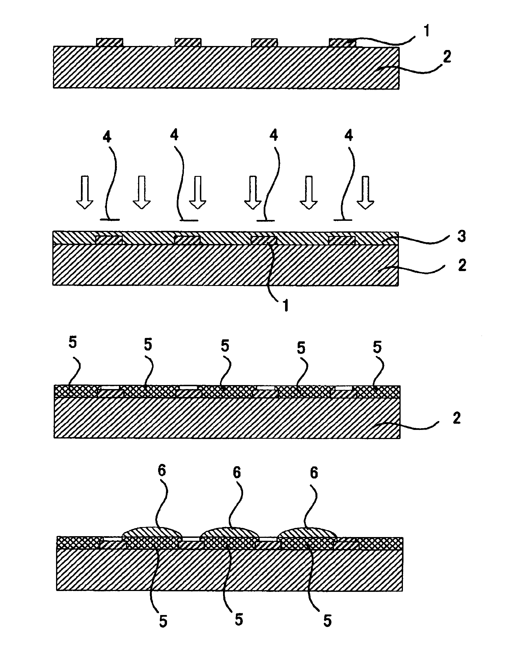
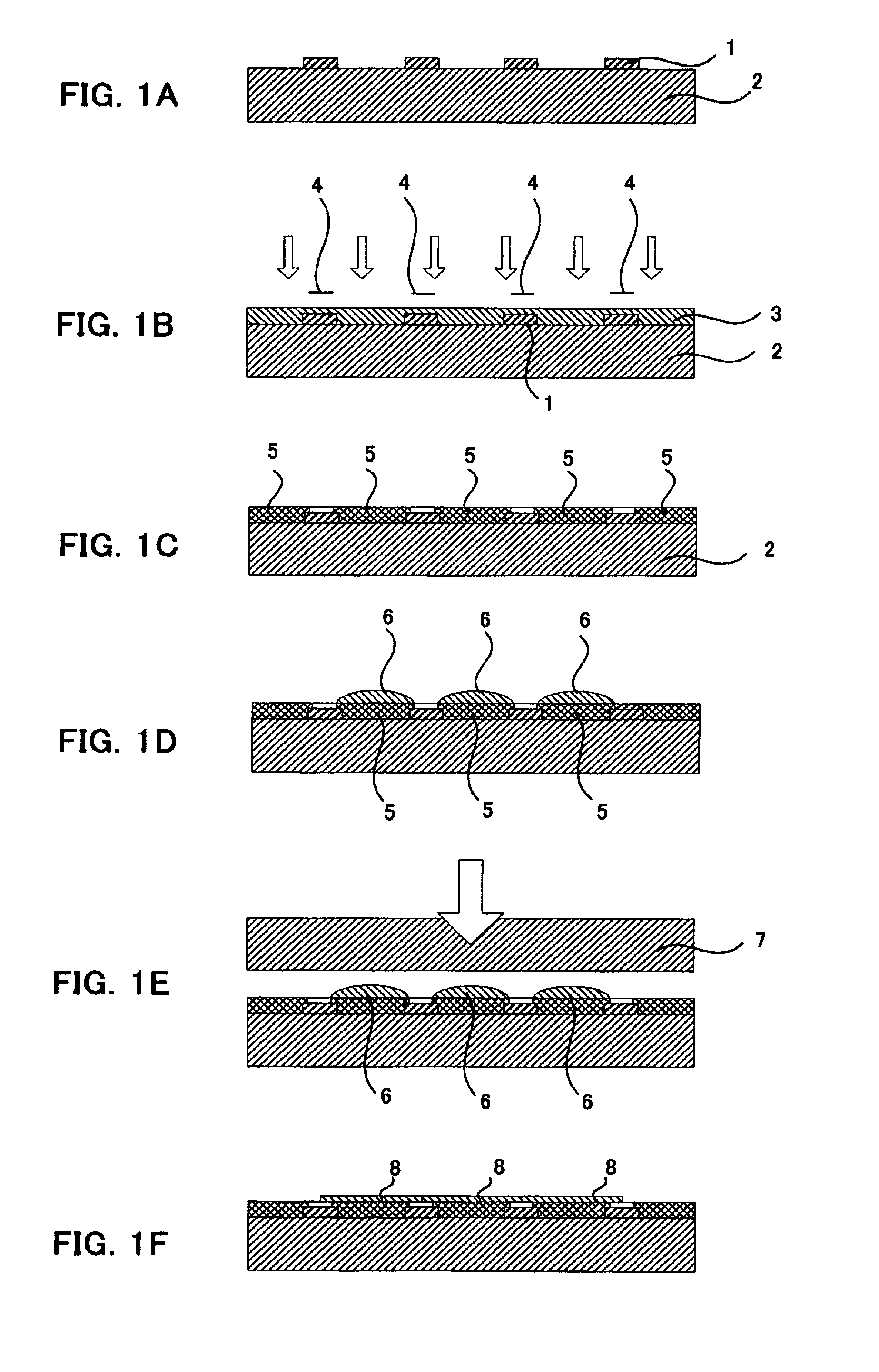
[0161]The solution was applied on a soda glass transparent substrate having a black matrix (light shielding part) comprising a chromium thin film pattern having a 0.7 mm thickness, a 90 μm×300 μm opening part, and a 30 μm line width, by spin coating. After heating at 150° C. for 20 minutes, a photocatalyst containing layer having a 0.15 μm thickness was obtained.

[0162]The contact angle of the photocatalyst containing layer with a we...


PUM

PropertyMeasurementUnit
contact angleaaaaaaaaaa
surface tensionaaaaaaaaaa
thicknessaaaaaaaaaa

Abstract

The main object of the present invention is to provide a method for manufacturing a color filter, capable of having the surface of the pixel part flatly even in the case a pixel part is formed by an ink discharging method, and the thickness of each pixel part evenly. In order to achieve the above-mentioned object, the present invention provides a method for manufacturing a color filter comprising at least a pixel part forming process of forming a pixel part of a plurality of colors in a predetermined pattern by adhering an ink on a transparent substrate by a discharging method, and the convex pixel part is formed in the pixel part forming process, wherein a pixel part flattening process of flattening the convex pixel part is executed after the pixel part forming process.

Description

BACKGROUND OF THE INVENTION[0001]1. Field of the Invention[0002]The present invention relates to a method for manufacturing a color filter suitable for a color liquid crystal display, capable of obtaining an even pixel part even in the case the pixel part is formed by an discharging method such as an ink jet method.[0003]2. Description of the Related Art[0004]Recently, accompanied by development of the personal computers, in particular, development of the portable personal computes, demand to liquid crystal displays, particularly color liquid crystal displays tends to be increasing. However, since color liquid crystal displays are expensive, decrease of the cost is highly requested. In particular, decrease of the cost of color filters, which accounts for a large proportion in terms of the cost, is highly requested.[0005]In general, such color filters comprises coloring pattern of the three primary colors of red (R), green (G) and blue (B). A liquid crystal functions as a shutter by ...

Claims


Application Information

Patent Timeline
Patent Type & Authority Patents(United States)
IPC IPC(8): G02B5/20B41J2/01G02F1/1335
CPCG02B5/201G02F1/133516G02B5/223
Inventor SONEHARA, AKIOKOBAYASHI, HIRONORINAKAMURA, NORIKATSU
Owner DAI NIPPON PRINTING CO LTD
Why Eureka
Try Eureka