Multi-state load switched power amplifier for polar modulation transmitter

a power amplifier and polar modulation technology, applied in the direction of amplifiers with modulators/demodulators, amplifiers with semiconductor devices/discharge tubes, gain control, etc., can solve the problems of high signal distortion, high dynamic range requirements, and conventional power amplifiers that cannot operate as efficiently as possible at high output power

Active Publication Date: 2007-02-27
GOOGLE TECHNOLOGY HOLDINGS LLC
View PDF10 Cites 31 Cited by
  • Summary
  • Abstract
  • Description
  • Claims
  • Application Information

AI Technical Summary

Benefits of technology

[0013]The instant disclosure is provided to further explain in an enabling fashion the best modes of performing one or more embodiments of the present invention. The disclosure is further offered to enhance an understanding and appreciation for the inventive principles and advantages thereof, rather than to limit in any manner the invention. The invention is defined solely by the appended claims including any amendments made during the pendency of this application and all equivalents of those claims as issued.

Problems solved by technology

In a polar modulation system, in addition to the usual power level control requirements, the dynamic range requirement is more demanding because the power amplifier must support an adequate dynamic range, from minimum value to maximum values.
The low power control signal magnitude can exacerbate issues caused by DC offsets in the amplitude path and carrier leakage in the power amplifier, leading to high levels of signal distortion.
Moreover, the conventional power amplifier does not operate as efficiently as possible at high output power, e.g., in EDGE mode, if an alternate higher output power mode, such as a GSM constant envelope mode is supported.
Further, the conventional power amplifier does not operate efficiently at reduced output power levels.

Method used


Image

  • Multi-state load switched power amplifier for polar modulation transmitter
  • Multi-state load switched power amplifier for polar modulation transmitter
  • Multi-state load switched power amplifier for polar modulation transmitter

Examples


Embodiment Construction

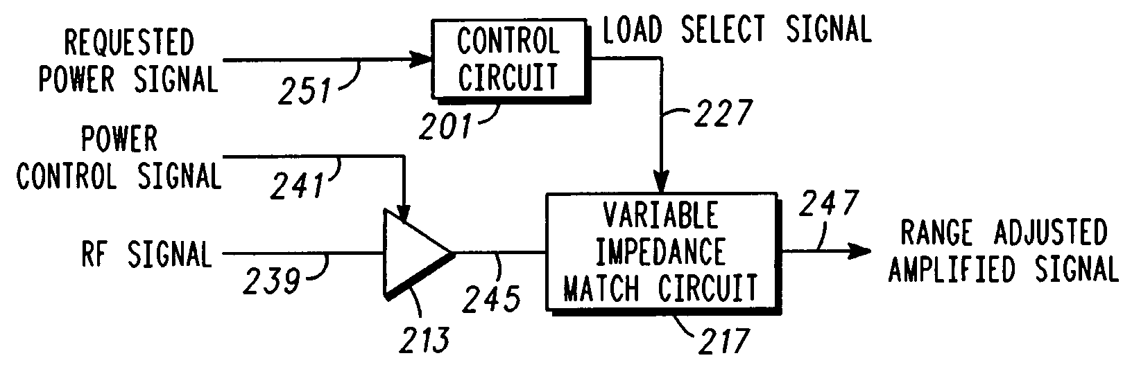
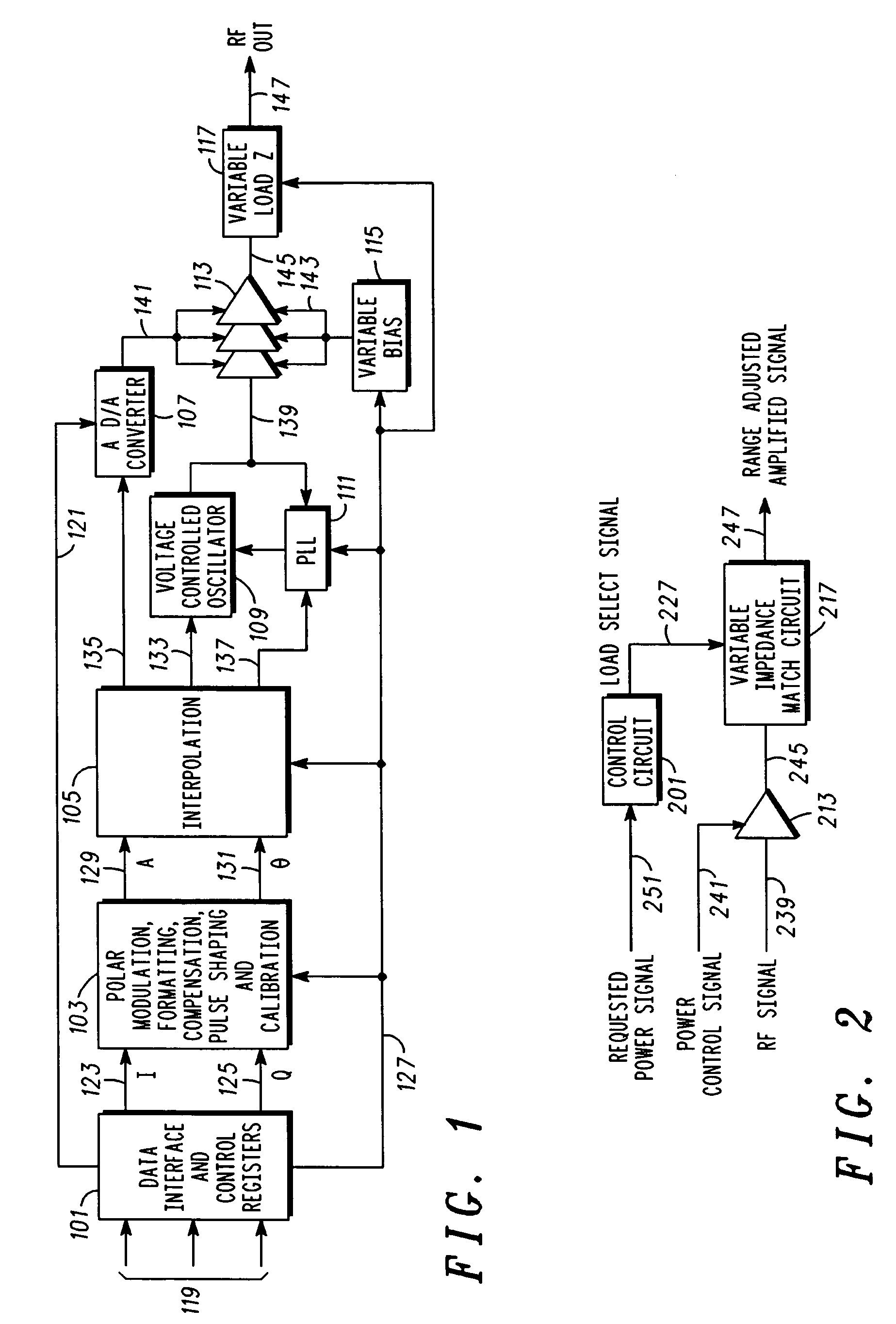
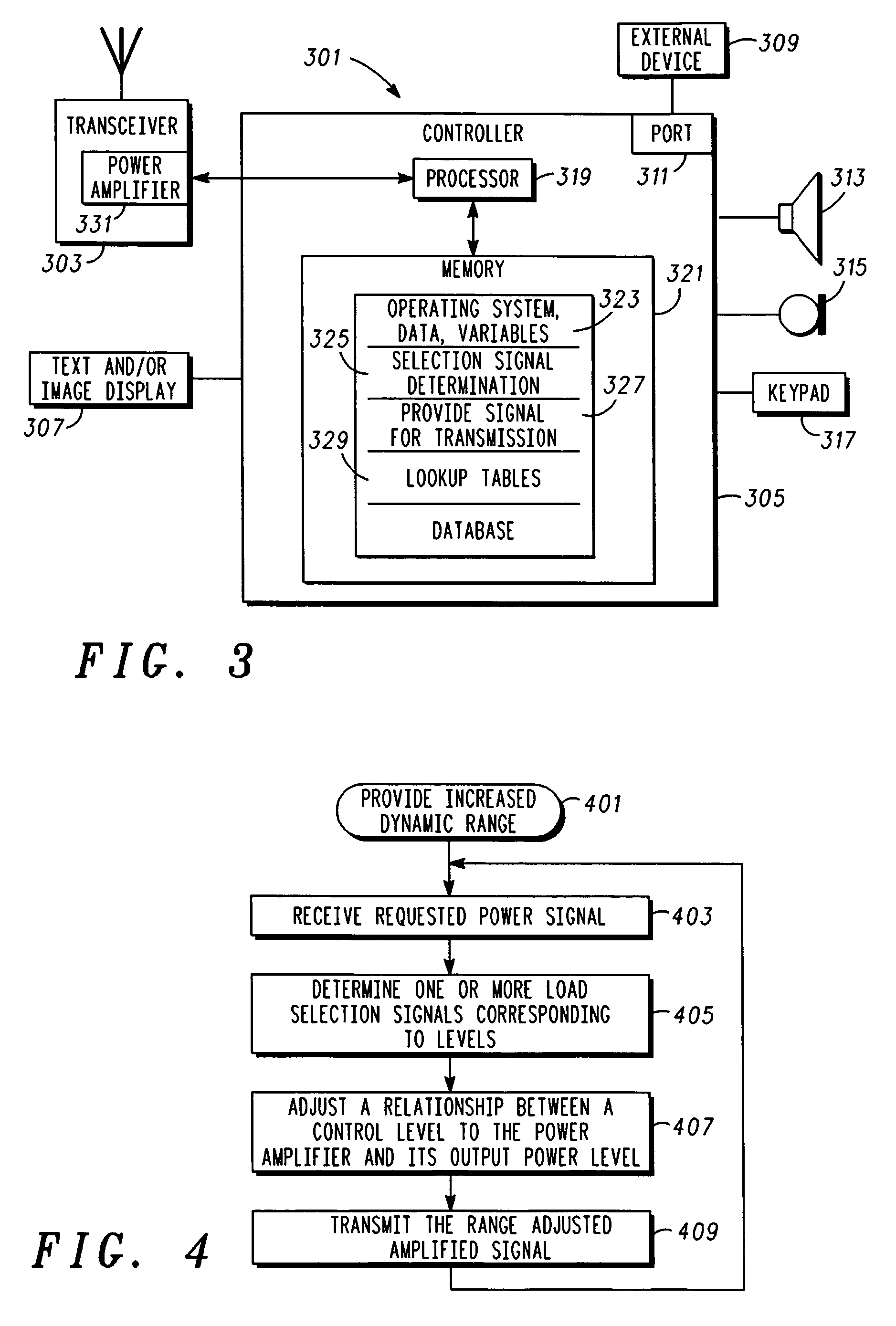
[0011]In overview, the present disclosure concerns wireless communications devices or units, often referred to as communication units, such as cellular phone or two-way radios and the like having a transmitter capability, or components thereof. Such communication units can be associated with a communication system such as an Enterprise Network, a cellular Radio Access Network, or the like. Such communication systems may further provide services such as voice and data communications services. More particularly, various inventive concepts and principles are embodied in systems, communication units, components therefore, and methods therein for modulating a signal to produce a range-adjusted signal, in association with a transmission from a communication unit.

[0012]It should be noted that the term communication unit may be used interchangeably herein with subscriber unit, wireless subscriber unit, wireless subscriber device or the like. Each of these terms denotes a device ordinarily a...


PUM


Abstract

A polar modulation power amplifier circuit includes a control circuit (101) to determine and provide a load selection signal (127), wherein the load selection signal (127) is determined responsive to a requested power signal (119). A power amplifier (113) is responsive to a power control signal (141), for amplifying an RF signal (139) to produce an amplified signal (145), having an output power level. A variable impedance matching circuit (117) is responsive to the load selection signal (127), to adjust a relationship between the control level and the output power level, to produce a range-adjusted amplified signal (147).

Description

FIELD OF THE INVENTION[0001]The present invention relates in general to wireless communication units and wireless networks, and more specifically to providing increased dynamic range in a polar modulation power amplifier circuit.BACKGROUND OF THE INVENTION[0002]In today's telecommunications industry, market forces are driving communication devices to support enhanced data rates as well as more efficient power consumption to conserve battery life. Much of the power in a communication device is consumed to support the power amplifier and associated circuits. Even when power ranges vary, power amplifiers should still operate at peak efficiency. In an effort to maximize efficiency, power amplifiers must operate near peak efficiency over the varying power ranges that can be called for in a communication device.[0003]Where the power amplifier is incorporated in a system with a polar modulation transmitter, the demands on the power amplifier can be higher in comparison to demands on a Cart...

Claims


Application Information

Patent Timeline
Patent Type & Authority Patents(United States)
IPC IPC(8): H03G3/20
CPCH03F1/02H03F1/0261H03F1/56H03F1/30H03F2200/387
Inventor KLOMSDORF, ARMIN W.BLACK, GREG R.SCHWENT, DALE G.
Owner GOOGLE TECHNOLOGY HOLDINGS LLC
Why Eureka
Try Eureka