Multi-band look-up table type predistorter

a multi-band look-up table and predistorter technology, applied in the direction of amplifier modifications to reduce non-linear distortion, digital transmission, baseband system details, etc., can solve the problems of bloated device scale, increased device bulkiness, and higher power consumption, so as to reduce power consumption, correct distortion compensation, and simplify the equipment configuration

Inactive Publication Date: 2007-02-27
NTT DOCOMO INC
View PDF10 Cites 49 Cited by
  • Summary
  • Abstract
  • Description
  • Claims
  • Application Information

AI Technical Summary

Benefits of technology

[0013]With the present invention, it is possible to achieve correct distortion compensation for each frequency band by separating the input signal containing multiple frequency band signals by means of band signal extractors into signals of the respective frequency bands and making compensation in each band on the basis of distortion compensation value that is read out of the look-up table provided for each band. In particular, since the signals of the respective frequency bands are combined by the combiner after being added with the corresponding compensation values, the combined output can be amplified by a common amplifier. This permits simplification of the equipment configuration, reduction of power consumption and equipment miniaturization.

Problems solved by technology

To transmit signals of multiple frequency bands while making distortion compensation of the signals by look-up table type predistortion processing, the look-up table type predistorter needs to be built for each frequency band, and a vector signal modulator, a frequency converter, and a power amplifier are also required for each band—this inevitably causes the defects of bloated device scale, higher power consumption and increased device bulkiness.
In the case of performing the look-up table type predistortion processing for multiple frequency bands by use of a single look-up table, however, if the bands are spaced far apart as compared with their bandwidths as in the cases of 800 MHz and 1.5 GHz, the compensation values prestored in the look-up table become uncertain for the signals of the both bands, making it impossible to correctly compensate for distortions occurring in the both bands.

Method used


Image

  • Multi-band look-up table type predistorter
  • Multi-band look-up table type predistorter
  • Multi-band look-up table type predistorter

Examples


embodiment 1

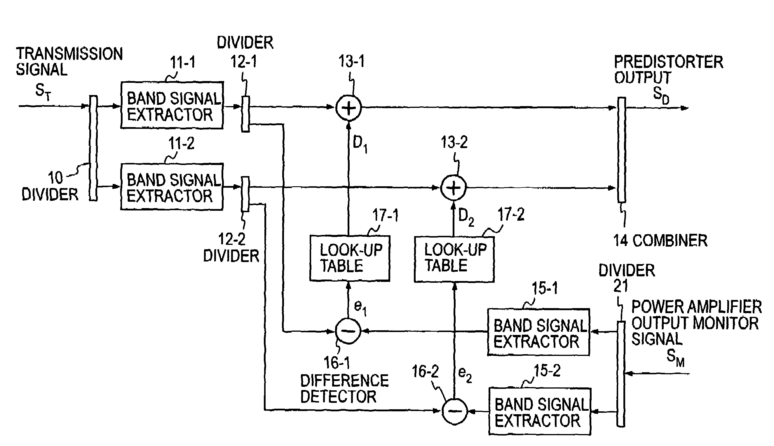
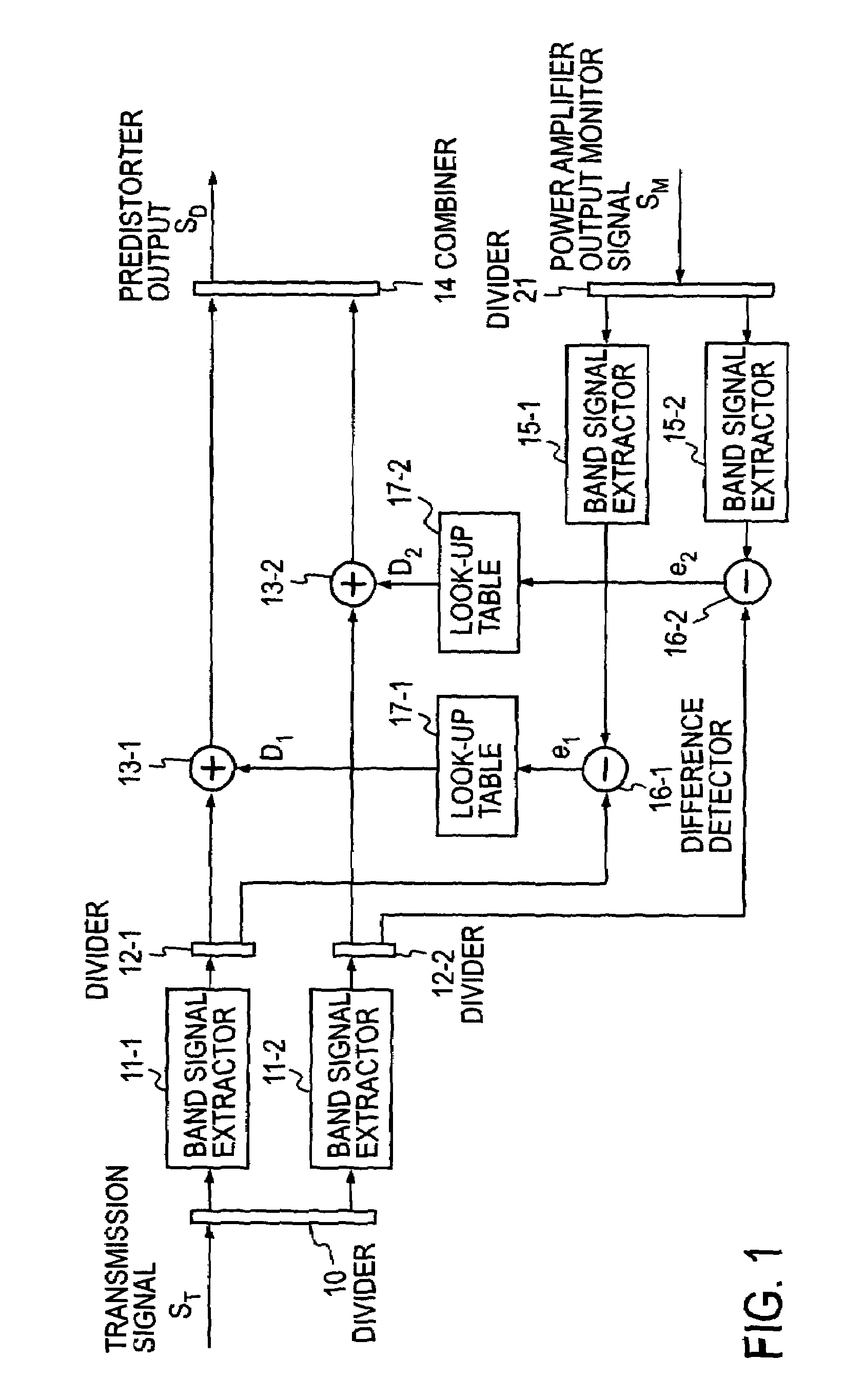
[0023]FIG. 1 illustrates in block form the basic configuration of the look-up table type predistorter that carries out the present invention in the best mode. The predistorter according to the present invention can be configured to handle signals of two or more discrete frequency bands, simultaneously. In the interests of brevity of description, the predistorter will hereinafter be assumed to be compatible with signals of two frequency bands.

[0024]The look-up table type predistorter according to the present invention is comprised of: band signal extractors 11-1 and 11-2 for extracting band signals from an input signal ST of two transmission frequency bands; difference detectors 16-1 and 16-2 for detecting differences between the band signals extracted by the band signal extractors 11-1 and 11-2 and signals of the corresponding frequency bands extracted from the output signal from the power amplifier (not shown) whose distortion is to be cancelled by the predistorter; frequency band ...

embodiment 2

[0035]FIG. 5 illustrates in block form a second embodiment of the present invention, in which the look-up table type predistorter, surrounded by the broken line is formed by digital circuits. Because of the digital signal processing system, I and Q signal paths are provided. At the input side two digital transmitters T-1 and T-2 are provided, from which a first frequency band signal ST1 of the center frequency f1 and a second frequency band signal ST2 of the center frequency f2 are input to the predistorter. In the application of the predistorter to mobile communications, the first and second frequency band signals of the center frequencies f1 and f2 may be 800-MHz and 1.5-GHz band signals, respectively. The input signals are not limited specifically to these two waves, but other frequency band signals such as 2-GHz, 5-GHz and so on can also be used.

[0036]The band signals output from the transmitters T-1 and T-2 are combined by a combiner 9, and the combined signal ST is input to th...

embodiment 3

[0043]FIG. 6 illustrates in block form another embodiment of the present invention, which is a multi-band look-up table type analog predistorter formed by analog circuits. Since the look-up tables 17-1 and 17-2 are implemented by digital signal processing, the reference signals are obtained by frequency converting high-frequency difference signals e1 and e2 by down converters 33-1 and 33-2 to base band signals and converting the base band signals by analog-to-digital converters (ADC) 43-1 and 34-2 to digital signals. The compensation data D1 and D2 read out of the look-up tables 17-1 and 17-2 are converted by digital-to-analog converters (DAC) 35-1 and 35-2 to analog signals, which are converted by up converters 36-1 and 36-2 to high-frequency signals D1 and D2, which are applied to the adders 13-1 and 13-2. The part surrounded by the broken line is basically identical with the FIG. 1 configuration except the above. In this embodiment the output from the predistorter is amplified by...


PUM


Abstract

A predistorter compensates, with high accuracy, for a distortion in each frequency band by a power amplifier that amplifies a transmission signal containing multiple frequency bands whose center frequencies are widely spaced apart. Signals of the respective frequency bands are extracted by multiple band signal extractors from the input signal containing transmission signals of multiple frequency bands; differences between the extracted signals and the output signal from the power amplifier are detected by multiple difference detectors in the respective bands; the detected difference signals are used as reference signals to read out compensation data from look-up tables for the respective frequency bands; the compensation data is added by multiple adders to the extracted transmission signals of the respective frequency bands; and the added outputs are combined by a combiner to provide the output signal from the predistorter.

Description

BACKGROUND OF THE INVENTION[0001]The present invention relates to a multi-band predistorter that permits amplification of all transmission signals of multiple frequency bands by a common amplifier.[0002]One of known compensation method for nonlinear distortions by microwave power amplifiers is a predistortion method using a digital signal processing scheme (hereinafter referred to as a digital predistortion method) (for example, Japanese patent application laid open No. 2002-522989, hereinafter referred to as patent document 1). The digital predistortion method features elimination of the need for complex analog circuitry by implementing a predistorter configuration through utilization of digital signal processing. Linear amplifier realizations have been achieved mostly by use of analog circuits such as a feed-forward amplifier, a negative feed-back amplifier, and so forth. Predistorters have also been formed by analog circuits (for example, H. Girard and K. Feher, “A New Baseband L...

Claims


Application Information

Patent Timeline
Patent Type & Authority Patents(United States)
IPC IPC(8): H03F1/26H04B1/62H03F1/32H03F3/189
CPCH03F1/3241H03F1/3247H03F3/189H03F1/3252H03F2201/3233H03F1/32H04B1/62
Inventor SUZUKI, YASUNORINARAHASHI, SHOICHI
Owner NTT DOCOMO INC
Why Eureka
Try Eureka