Master-oscillator power-amplifier (MOPA) excimer or molecular fluorine laser system with long optics lifetime

a technology of power amplifier and laser system, which is applied in the direction of laser details, optics, instruments, etc., can solve the problems of sub-micron features, increased complexity and expense, and requirements of semiconductor manufacturers for higher power and tighter bandwidth

Active Publication Date: 2007-02-27
COHERENT GMBH
View PDF15 Cites 26 Cited by
  • Summary
  • Abstract
  • Description
  • Claims
  • Application Information

AI Technical Summary

Problems solved by technology

The desire for such submicron features comes with a price, however, as there is a need for improved processing equipment capable of consistently and reliably generating such features.
Further, as excimer laser systems are the next generation to be used for micro-lithography applications, the demand of semiconductor manufacturers for powers of 40 W or more to support throughput requirements leads to further complexity and expense.
Requirements of semiconductor manufacturers for higher power and tighter bandwidth can place excessive, and often competing, demands on current single-chamber-based light sources.
A major limitation to deep-UV (DUV) excimer laser systems is the lifetime of the optical components used therein.
Especially at the level of output power on the order of tens of Watts, fast decay of optical components increases downtime as well as operational costs for applications such as microlithography.
While implementation of the MOPA concept can increase the output power of the laser system, one of fundamental limitations of existing MOPA systems is this relatively short optics lifetime.
For example, one of the principal factors limiting the optics lifetime in a MOPA system is the fast degradation of the output window of the amplifier discharge chamber, as this optical component is typically at the point where the power is at the highest level.

Method used


Image

  • Master-oscillator power-amplifier (MOPA) excimer or molecular fluorine laser system with long optics lifetime
  • Master-oscillator power-amplifier (MOPA) excimer or molecular fluorine laser system with long optics lifetime
  • Master-oscillator power-amplifier (MOPA) excimer or molecular fluorine laser system with long optics lifetime

Examples


Embodiment Construction

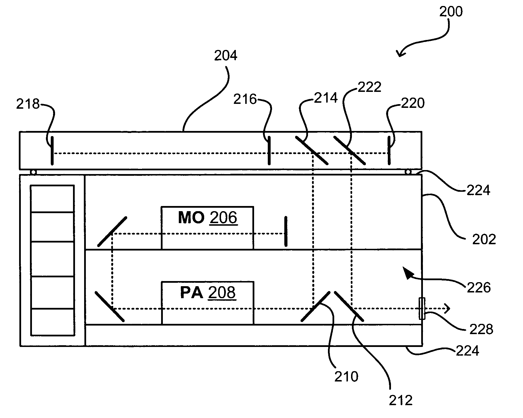
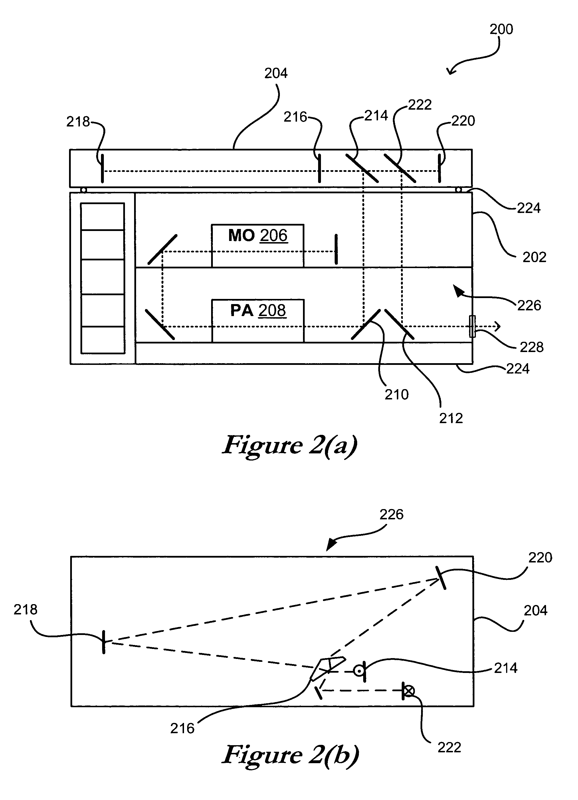
[0021]Systems and methods in accordance with various embodiments of the present invention can employ any of a number of optical layouts and approaches in order to increase the lifetime of various system optics. These approaches can include, for example, reducing the average power density and peak intensity of a beam (or optical pulse) that passes through these optical components. This reduction can be significant for those optical components, as a high-power beam output from an amplifier in a MOPA system such as that shown in FIG. 1 can reach a power level on the order of 100 W, which can lead to significant degradation of the optical components.

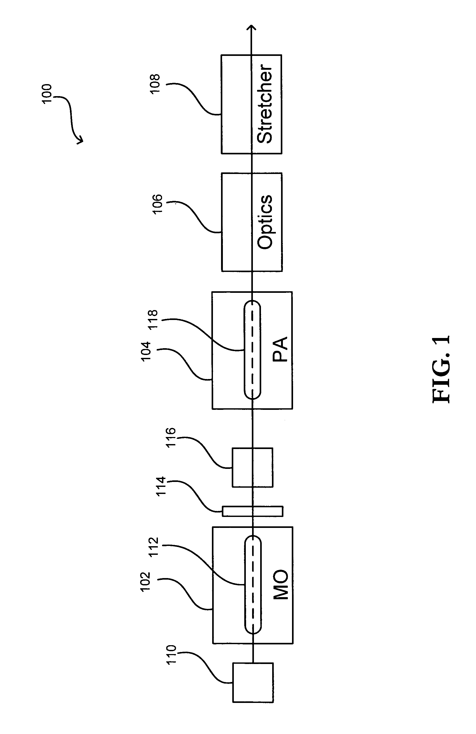
[0022]FIG. 1 shows a top view block diagram of an exemplary optical layout 100 that can be used with a MOPA system in accordance with one embodiment of the present invention. Various other MOPA configurations, as well as detail regarding the workings of MOPA systems, are disclosed in pending U.S. patent application Ser. No. 10 / 696,979, filed...


PUM


Abstract

The lifetime of optical components used in deep-UV (DUV) excimer laser systems, including systems in a MOPA configuration, can be increased by reducing the intensity of pulses incident upon these components. In one approach, an output pulse can be “stretched” in order to reduce the peak power of the pulse. A pulse stretching component can be used, which can be mounted outside the laser enclosure with a horizontal beam path in order to provide a delay line with a minimum impact on the laser system footprint. The horizontal beam path also can minimize the number of optical components in the arm containing the high power beam. A beamsplitting prism can be used with the delay line to avoid the rapid degradation of coatings otherwise exposed to intense UV beams. The prism can expand the beam in the delay line in order to minimize beam intensity and losses due to reflection.

Description

CLAIM OF PRIORITY[0001]This application claims priority to U.S. Provisional Application No. 60 / 484,046, filed Jul. 1, 2003, as well as U.S. Provisional Application No. 60 / 484,929, filed Jul. 3, 2003, each of which is hereby incorporated herein by reference.TECHNICAL FIELD OF THE INVENTION[0002]The present invention relates to a Master-Oscillator Power-Amplifier (MOPA) excimer or molecular fluorine laser system, particularly a MOPA system having optics with a relatively long lifetime.BACKGROUND[0003]Semiconductor manufacturers are currently using deep ultraviolet (DUV) lithography tools based on KrF-excimer laser systems, operating at wavelengths around 248 nm, as well as ArF-excimer laser systems, which operate at around 193 nm. Vacuum UV (VUV) tools are based on F2-laser systems operating at around 157 nm. These relatively short wavelengths are advantageous for photolithography applications because the critical dimension, which represents the smallest resolvable feature size that c...

Claims


Application Information

Patent Timeline
Patent Type & Authority Patents(United States)
IPC IPC(8): H01S3/00H01S3/22H01S3/10
CPCH01S3/0057G03F7/7055H01S3/0835H01S3/235
Inventor GOVORKOV, SERGEI V.HUA, GONGXUEMISURYAEV, TIMURWIESSNER, ALEXANDER O.SCHMIDT, THOMASPAETZEL, RAINER
Owner COHERENT GMBH
Why Eureka
Try Eureka