
Miniaturized microscope array digital slide scanner

a microscope array and digital slide technology, applied in the field of light microscopy, can solve the problems of time-consuming scanning process, and achieve the effect of rapid scanning

Inactive Publication Date: 2007-02-27
THE ARIZONA BOARD OF REGENTS ON BEHALF OF THE UNIV OF ARIZONA +1
View PDF44 Cites 49 Cited by
  • Summary
  • Abstract
  • Description
  • Claims
  • Application Information

AI Technical Summary

Benefits of technology

[0007]One object of the present invention is to provide an imaging system which can rapidly scan microscopy specimens and produce a composite image of entire specimens.
[0008]Another object of the present invention is to provide an imaging system with near diffraction-limited optical performance such that the clarity of the images is not degraded by wave-front aberrations, ray aberrations, or chromatic aberrations.
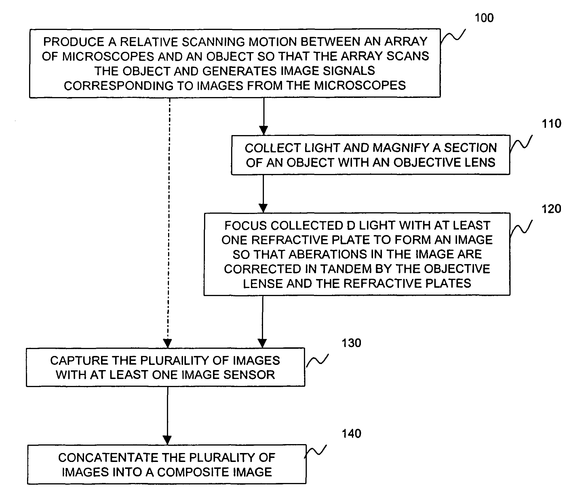
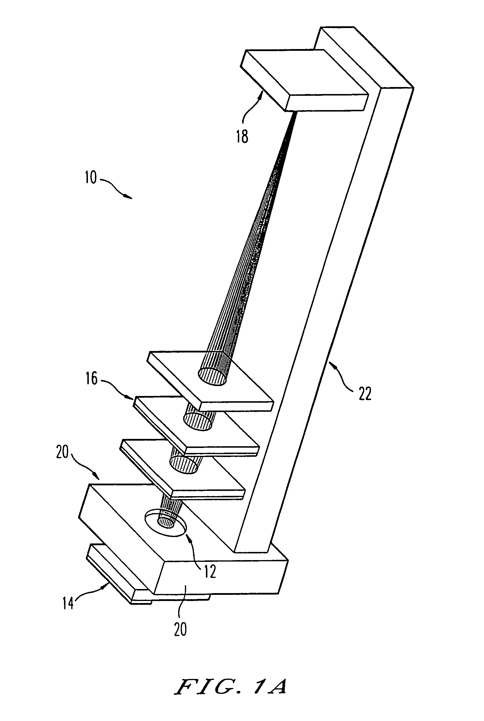
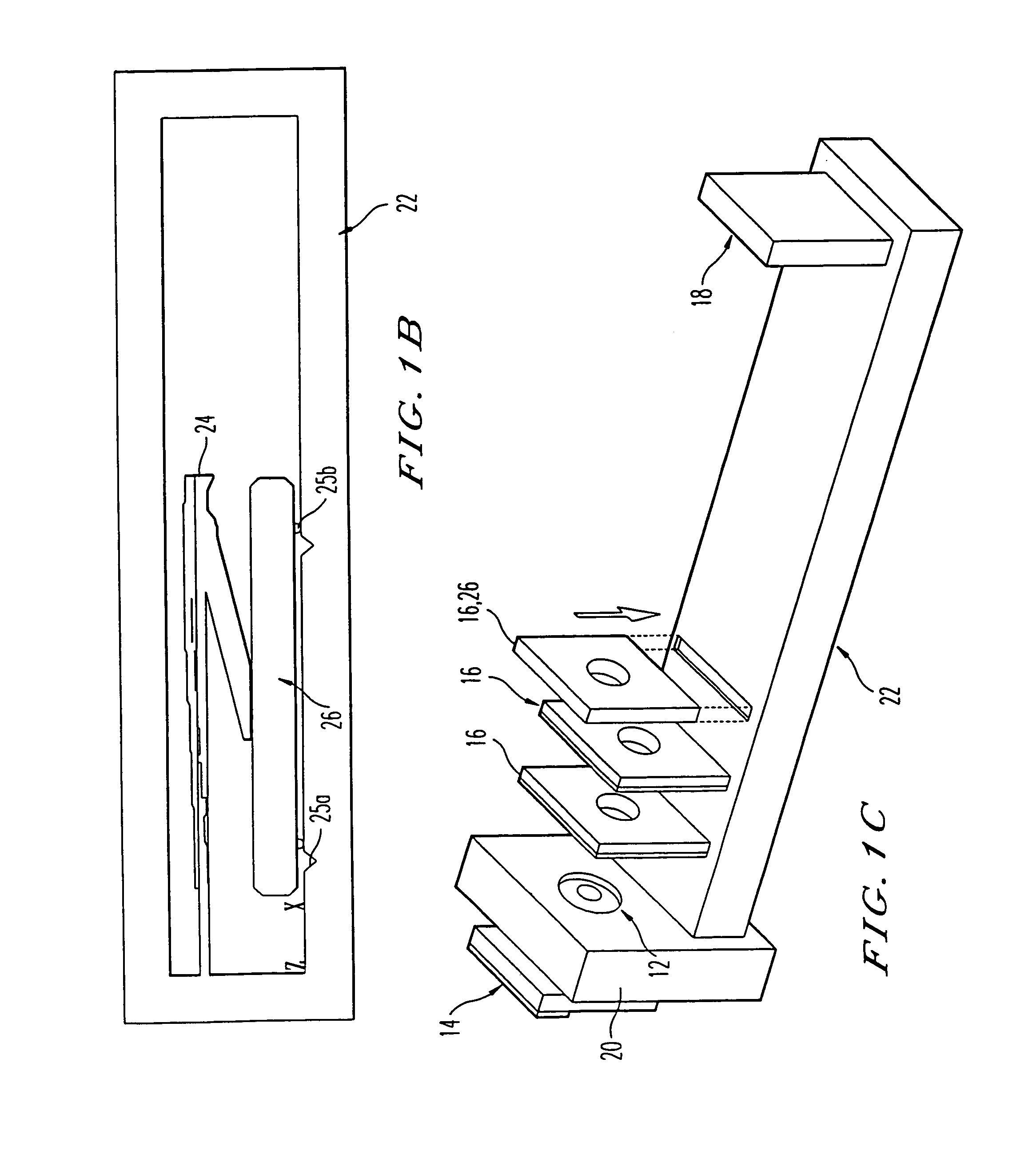
[0028]According to one aspect of the present invention, the optical axes of the microscope are arranged on a staggered grid such that a field of view of one microscope in a column partially overlaps a field of view of another microscope in the column if translated longitudinally. According to another aspect of the present invention, the MA is configured to translate both longitudinally along the length of the object and axially away from the object. The translational motion scans the microscope slide to generate individual images of the object which can be concatenated into a composite image. The axial motion permits focusing and scans of thick objects or objects of varying topography such that scans at different axial heights above the sample can yield, when processed, a composite three-dimensional image of the object.

Problems solved by technology

To image an entire standard microscope slide (i.e., a 20 mm by 50 mm microscope slide) requires a conventional light microscope to scan back and forth multiple times. The scanning process is time intensive.

Method used


Image

  • Miniaturized microscope array digital slide scanner
  • Miniaturized microscope array digital slide scanner
  • Miniaturized microscope array digital slide scanner

Examples


Embodiment Construction

[0059]Early techniques for scanning slides of pathological specimens relied on a single microscope objective and were frustrated by the time required to repetitively image at high magnification small portions of the specimen and step across the entire surface of the specimen. These systems were further frustrated by slow data transfer rates available at the time. For example, typical video frame transfer rates were approximately 6 MHz whereas presently digital data bus transfer data at rates near 100 MHz.

[0060]Meanwhile the MA of the present invention alleviates these problems. Images of an entire specimen can be acquired in a reasonable time frame. The pathologist can, if desired, inspect the entire specimen, and reexamine suspect areas of the specimen. With the near 100 MHz transfer rates available on present computers, it is possible to collect and concatenate images from the entire specimen and produce monochromatic and polychromatic images of the pathological specimen within se...


PUM


Abstract

An array of microscopes and a method of imaging an object with the array of microscopes. The array includes a plurality of optical elements being individually disposed with respect to a corresponding image plane and configured to image respective sections of an object, and includes a plurality of image sensors corresponding to respective optical elements and configured to capture corresponding representations of the respective sections of the object. The method includes imaging respective sections of an object with a plurality of optical elements and capturing corresponding representations of sections of the object from a plurality of image sensors.

Description

CROSS REFERENCE TO RELATED APPLICATIONS[0001]This application claims benefit of priority under 35 U.S.C. §119 to U.S. Provisional Application No. 60 / 276,498 filed on Mar. 19, 2001, the entire contents of which are incorporated by reference.BACKGROUND OF THE INVENTION[0002]1. Field of the Invention[0003]The present invention relates to the field of light microscopy. More particularly, this invention relates to a microscope array for scanning an object at high resolution or projecting a pattern onto a surface of an object.[0004]2. Description of the Related Art[0005]Pathologists are physicians responsible for analyzing tissue specimens, fine-needle aspirates of tissues, cytology specimens, and liquid specimens such as urine and blood by light microscopy. Analysis of specimens frequently is accomplished by viewing specimens on slides through a light microscope or by viewing electronic images of the specimens on a video monitor. Video images can be obtained by mounting a video camera on...

Claims


Application Information

Patent Timeline
IPC IPC(8): G06T5/50G02B21/18G02B21/00G02B21/36
CPCG02B21/36G02B21/002G02B21/367
Inventor WEINSTEIN, RONALD S.DESCOUR, MICHAEL R.LIANG, CHENBARTELS, PETER H.SHACK, ROLAND V.
Owner THE ARIZONA BOARD OF REGENTS ON BEHALF OF THE UNIV OF ARIZONA
Learn More