Transient suppressor and power converter employing the same

a transient suppressor and power converter technology, applied in the direction of emergency protective arrangements for limiting excess voltage/current, electrical equipment, etc., can solve the problems of power loss in the diodes, reverse recovery of the rectifying diodes, and excess energy storag

Active Publication Date: 2007-03-06
ABB (SCHWEIZ) AG
View PDF6 Cites 12 Cited by
  • Summary
  • Abstract
  • Description
  • Claims
  • Application Information

AI Technical Summary

Benefits of technology

[0012]In yet another embodiment, the present invention provides a power converter including a transformer having a primary winding and a secondary winding, and a primary circuit coupled to the primary winding. The power converter also includes a rectifier coupled to an output filter circuit, and a transient suppressor coupled between the rectifier and the secondary winding. The transient suppressor includes a saturable reactor circuit interposed between the rectifier and the secondary winding. The transient suppressor also includes a RC circuit, coupled across the secondary winding, that cooperate with the saturable reactor circuit to suppress a peak voltage associated with the rectifier.

Problems solved by technology

Unfortunately, rectifying diodes suffer from a reverse recovery condition when there is a transition from a conduction stage to a non-conduction stage.
During the reverse recovery condition, the current through the diodes reverse direction, causing excess energy to be stored in the leakage inductance of an isolation transformer and power to be lost in the diodes.
The energy stored in the leakage inductance is dissipated in a resonant manner with the junction capacitance of the rectifying diode, causing oscillation (or ringing) and overshoot in the voltage waveform of the rectifying diode.
As a result, the converter suffers efficiency losses that impair the overall performance of the converter.
As the output power increases, the power dissipated in the snubber resistor becomes significant thereby limiting the RCD snubber to lower power applications.
However, the snubber circuit will lose its effectiveness if the converter is operated at very small duty ratio, resulting in insufficient time to discharge the energy stored in the snubber circuit.
However, when the rectifying diode transitions from conduction to non-conduction stage and the reverse recovery condition occurs, the reactor provides a high impedance thereby reducing the reverse current flow.
The saturable reactor has to be cooled by forced air, otherwise the reactor will run too hot.
When applied to natural convection cooling power supplies, the temperature rise (e.g., up to 1200 Celsius) may not be acceptable.
Unfortunately, the clamp circuit introduced in Todd is generally limited to applications wherein the output voltage of the converter is fixed.
An impediment to the use of such a circuit is that the coupling transformer of the clamp circuit is generally comparable in size to the main transformer due to the large volts-second of the main transformer.

Method used


Image

  • Transient suppressor and power converter employing the same
  • Transient suppressor and power converter employing the same
  • Transient suppressor and power converter employing the same

Examples


Embodiment Construction

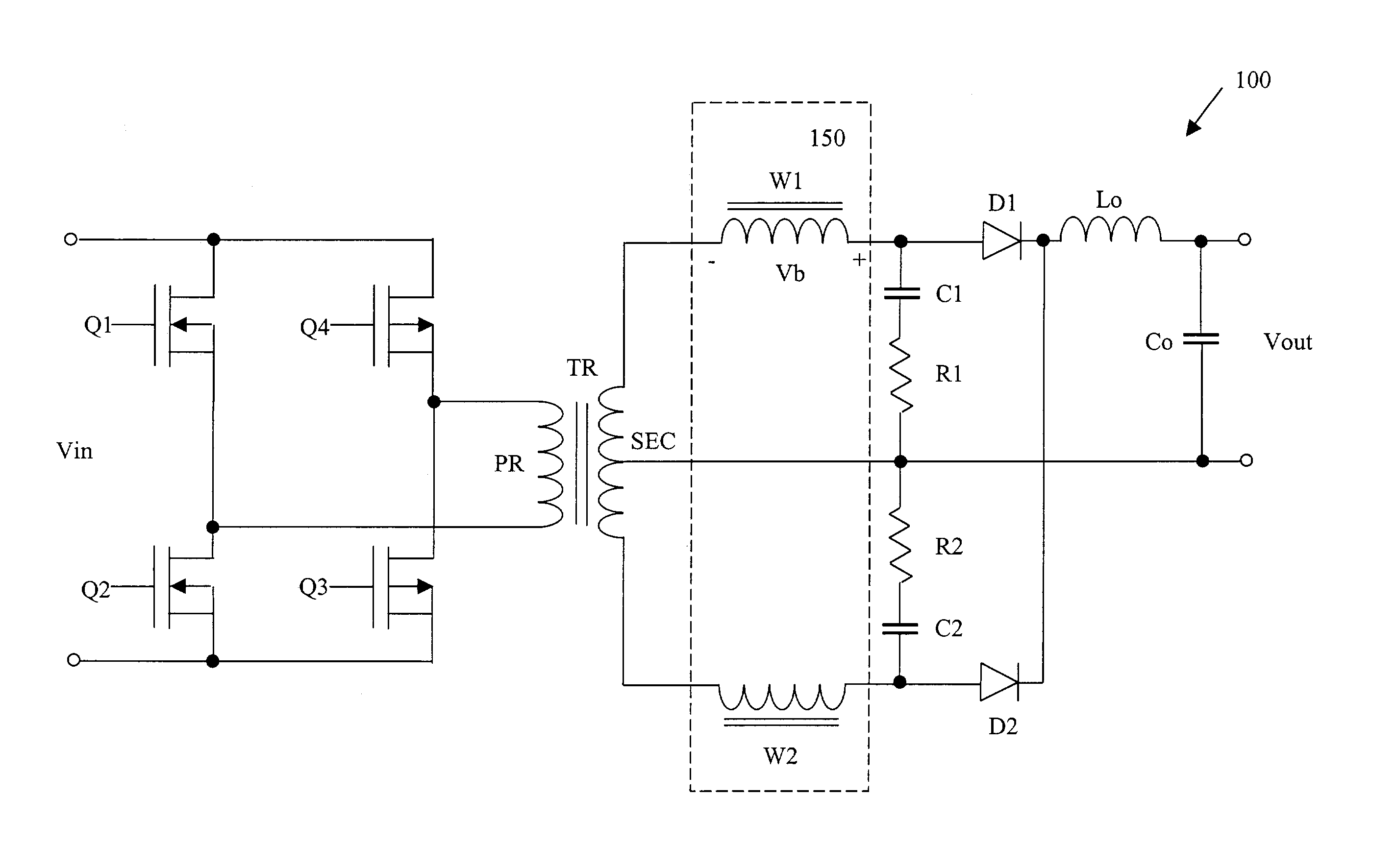
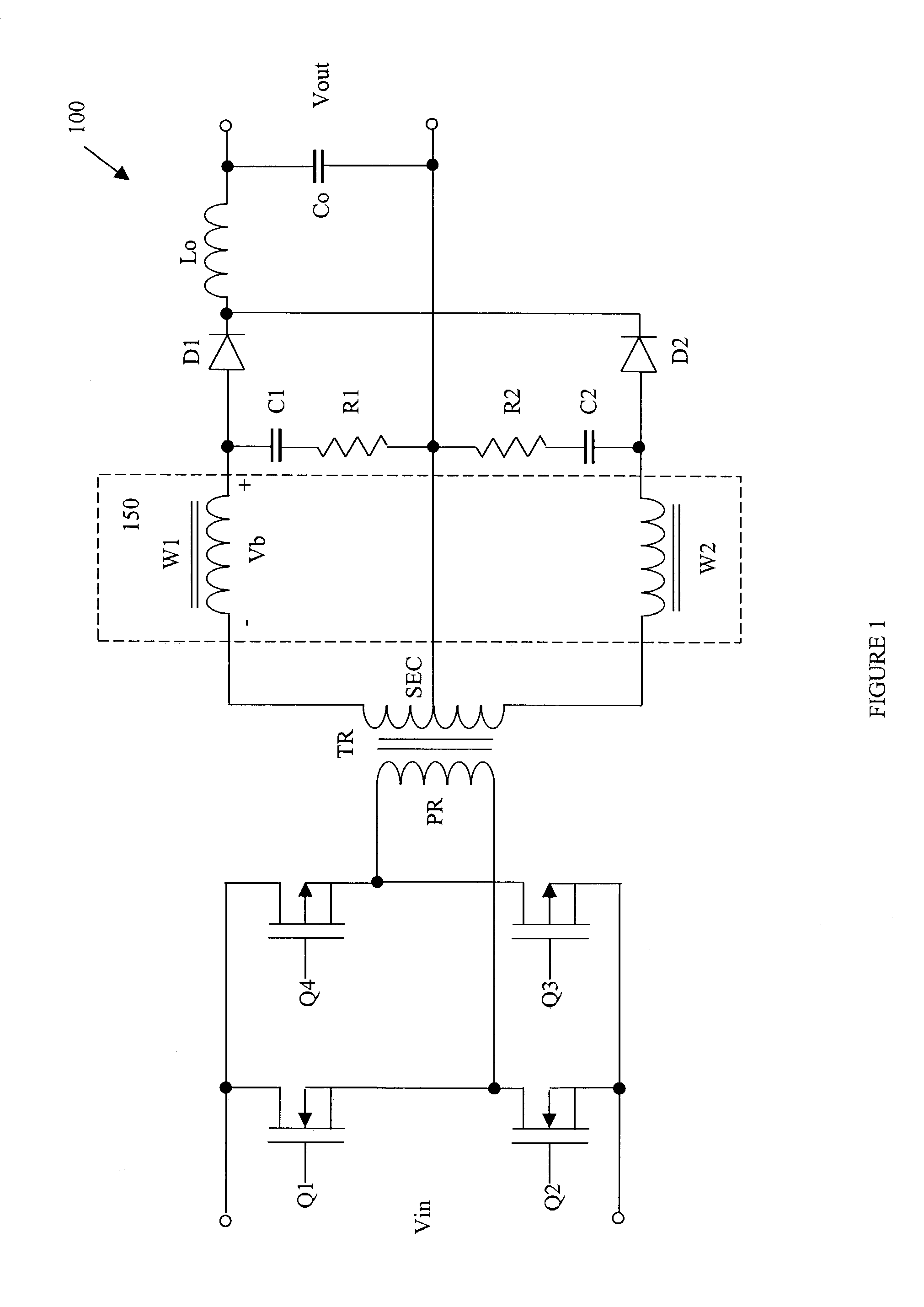
[0017]Referring initially to FIG. 1, illustrated is a schematic diagram of an embodiment of a power converter 100 constructed according to the principles of the present invention. While the power converter 100 in the illustrated embodiment employs a full-bridge topology, other types of converter topologies are well within the broad scope of the present invention.

[0018]The power converter 100 is coupled to a source of electrical power and provides an output voltage Vout to a load coupled to an output thereof. The power converter 100 includes a transformer TR having a primary winding PR and a center tapped secondary winding SEC. The power converter 100 also includes a primary circuit having first, second, third and fourth switches Q1, Q2, Q3, Q4 controllable by a control circuit (not shown) to transfer power from the source of electrical power to the load. The power converter 100 also includes a rectifier having first and second rectifying diodes D1, D2 and an output filter circuit ha...


PUM


Abstract

The present invention is directed to a transient suppressor, a method of suppressing a peak voltage associated with a rectifier, and a power converter employing the same. In one embodiment, the transient suppressor includes a saturable reactor circuit interposed between a rectifier and a transformer winding. The transient suppressor also includes a RC circuit, coupled between the rectifier and the saturable reactor circuit and across the transformer winding, configured to cooperate with the saturable reactor circuit to suppress a peak voltage associated with the rectifier.

Description

TECHNICAL FIELD OF THE INVENTION[0001]The present invention is directed, in general, to power electronics and, more specifically, to a transient suppressor, a method of suppressing a peak voltage associated with a rectifier, and a power converter employing the same.BACKGROUND OF THE INVENTION[0002]A power converter is a power processing circuit that converts an input voltage waveform into a specified output voltage waveform. In many applications requiring a DC output, switched-mode DC / DC converters are frequently employed to advantage. DC / DC converters generally include an inverter, an input / output isolation transformer and a rectifier on a secondary side of the isolation transformer. The inverter generally includes a switching device, such as a field effect transistor (“FET”), that converts the DC input voltage to an AC voltage. The input / output isolation transformer, then, transforms the AC voltage to another value and the rectifier generates the desired DC voltage at the output o...

Claims


Application Information

Patent Timeline
Patent Type & Authority Patents(United States)
IPC IPC(8): H02H3/22H02H7/125
CPCH02H9/005H02H7/125
Inventor CHEN, DAOSHEN
Owner ABB (SCHWEIZ) AG
Why Eureka
Try Eureka