
Current interpolation in multi-phase local oscillator for use with harmonic rejection mixer

a local oscillator and mixer technology, applied in pulse manipulation, baseband system details, pulse technique, etc., can solve the problems of difficult filtering or otherwise eliminating harmonics that are close in frequency to the fundamental frequency, affecting the frequency of different lo frequencies, and severely restricting the number of phases available for a particular lo frequency

Active Publication Date: 2007-03-06
TEXAS INSTR INC
View PDF13 Cites 15 Cited by
  • Summary
  • Abstract
  • Description
  • Claims
  • Application Information

AI Technical Summary

Benefits of technology

The patent describes a circuit that reduces harmonic content in an output signal. It uses an oscillator circuit and a harmonic rejection mixer to create an emulated sinusoidal signal with minimal harmonic content. The circuit can produce a large number of output signals with different phases, and weights them to create a more accurate representation of the desired signal. This results in a more reliable and accurate output signal with reduced harmonic content.

Problems solved by technology

Undesirably, conventional square wave LOs generate a significant amount of odd harmonics.
Unfortunately, these harmonics mix with the modulated information signals.
Harmonics that are close in frequency to the fundamental frequency are difficult to filter or otherwise eliminate, using conventional techniques.
Unfortunately, such conventional arrangements severely limit the number of phases available for a particular LO frequency.
In Weldon's example, only four phases are produced at the LO output, substantially limiting the closeness with which a LO output can emulate a sinusoidal output, thus frustrating rejection of higher harmonics.
This need could be fulfilled by providing an HRM output that more closely emulates a sinusoidal signal, but with the limited number of LO phases available in conventional arrangements, this need has not been fulfilled.
Furthermore, Weldon's conventional 4-phase generation method is not applicable for all possible LO frequencies.

Method used


Image

  • Current interpolation in multi-phase local oscillator for use with harmonic rejection mixer
  • Current interpolation in multi-phase local oscillator for use with harmonic rejection mixer
  • Current interpolation in multi-phase local oscillator for use with harmonic rejection mixer

Examples


Embodiment Construction

[0019]In describing embodiments illustrated in the drawings, specific terminology is employed for the sake of clarity. However, the invention is not intended to be limited to the specific terminology so selected, and it is to be understood that each specific element includes all technical equivalents that operate in a similar manner to accomplish a similar purpose. Various terms that are used in this specification are to be given their broadest reasonable interpretation when used in interpreting the claims.

[0020]Moreover, features and procedures whose implementations are well known to those skilled in the art are omitted for brevity. For example, design, selection, and implementation of basic electronic circuit elements such as signal level shifters, buffers, load balancing elements, grounding elements, bias elements, current mirror arrangements, logic elements, current and voltage sources, metal oxide semiconductor field effect transistors (MOSFETs), diodes (including “MOSFET diode...


PUM


Abstract

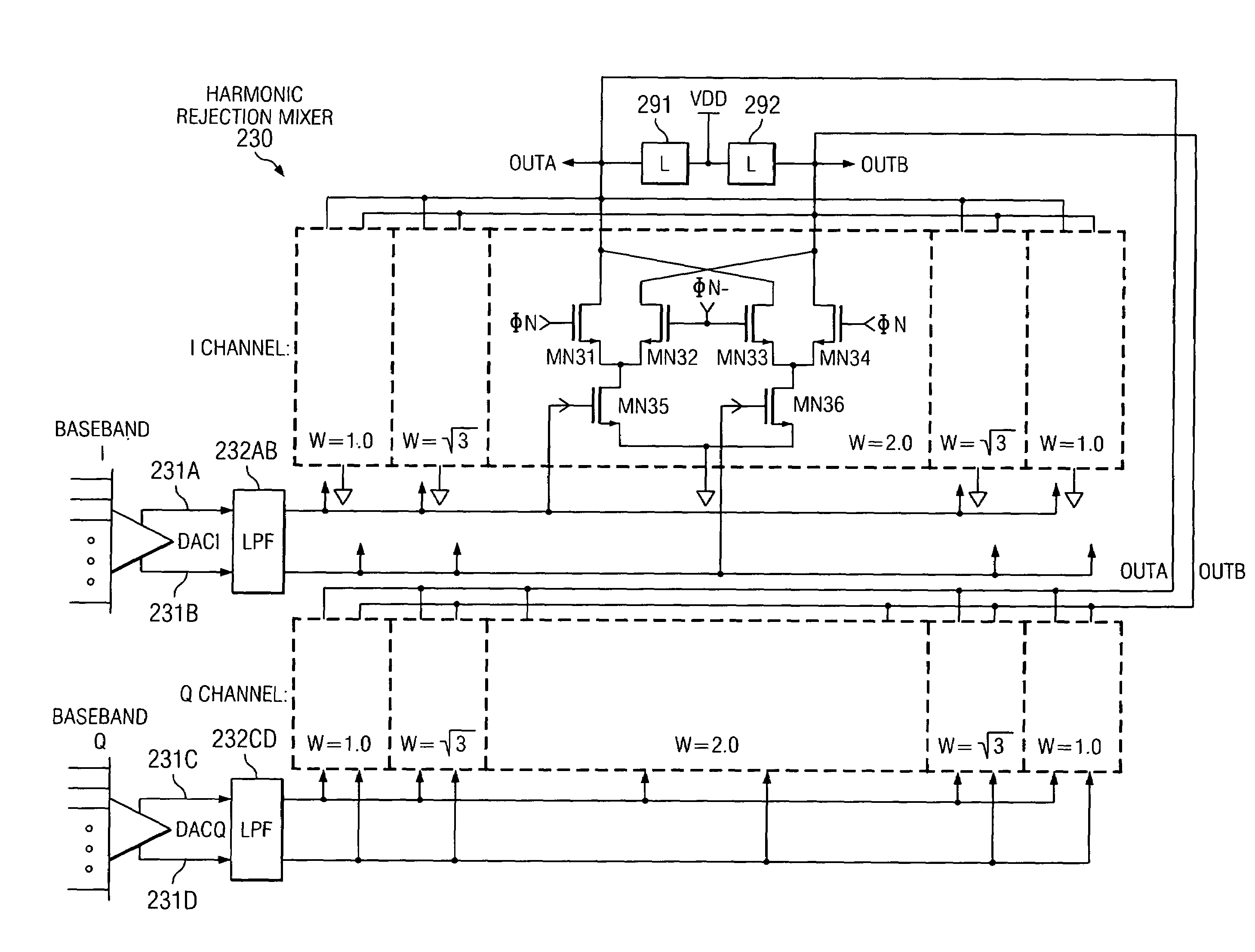
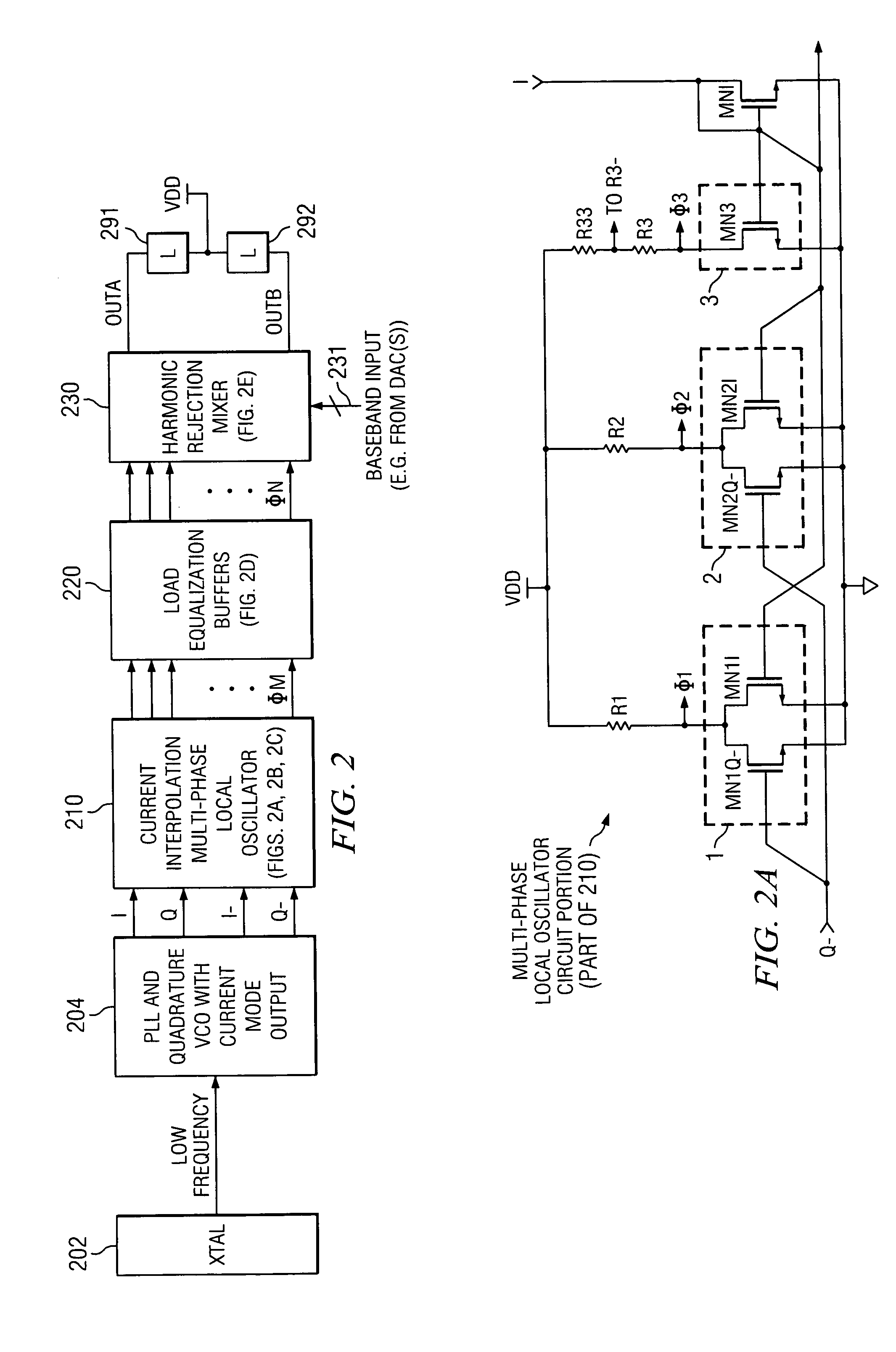
A circuit provides a reduced harmonic content output signal OUTA and / or OUTB that is modulated according to an input signal 231. The circuit has an oscillator circuit 210 and a harmonic rejection mixer (HRM) 230. The oscillator circuit 210 includes at least one “circuit portion” (FIG. 2A) configured to receive first and second orthogonal oscillator input signals (two of I, I−, Q, Q−) having respective first and second phases, and to provide an arbitrarily large number of oscillator output signals (φM) having respective mutually distinct phases that are interpolated between the first and second phases. Harmonic rejection mixer 230 is configured to use the input signal to modulate a combination of the oscillator output signals, the oscillator output signals being respectively weighted so as to provide an emulated sinusoidal signal constituting the reduced harmonic content output signal.

Description

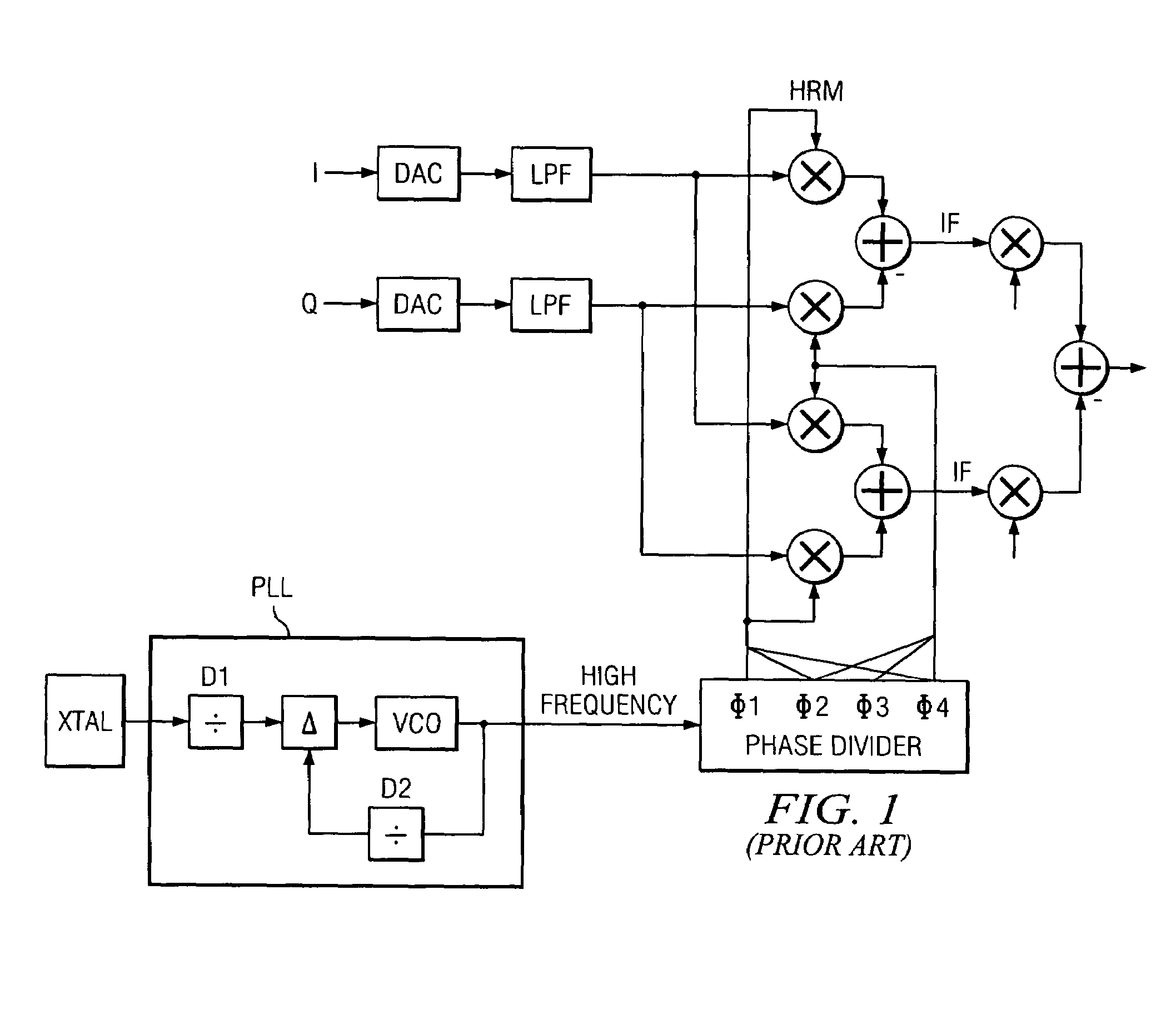
BACKGROUND OF THE INVENTION[0001]1. Field of the Invention[0002]The invention generally relates to generation of differently phased oscillator signals for use in harmonic rejection mixers (HRMs). More particularly, the invention relates to providing HRMs with an arbitrarily large number of differently-phased local oscillator (LO) signals to reject substantially more harmonics (“images”) than conventional arrangements, especially using LO signals that are not dependent on phase lock loop (PLL) frequency dividers to divide a high-frequency signal to a suitable LO frequency.[0003]2. Related Art[0004]Harmonic-rejection mixers (HRMs), which are designed to reject local oscillator (LO) harmonics (or “images”), are known in the art. See, for example, “A 1.75 GHz Highly-Integrated Narrow-Band CMOS Transmitter with Harmonic-Rejection Mixers” Weldon, J. A.; Rudell, J. C.; Lin, L; Narayanaswami, R. S.; Otsuka, M.; Dedieu, S; Tee, L.; Tsai, K-C; Lee, C-W; and Gray, P. R.; Section 10.4 of Digest...

Claims


Application Information

Patent Timeline
Patent Type & Authority Patents(United States)
IPC IPC(8): H04B1/26H03B27/00H03D7/14H04B1/10
CPCH03B27/00H03D7/1441H03D7/1475H03D7/1483H03D7/165H03D7/1458H03D2200/0086H03D2200/0033
Inventor LIN, HENG-CHIHGHARPUREY, RANJIT
Owner TEXAS INSTR INC
Learn More