
Illuminator for photodynamic therapy

Inactive Publication Date: 2007-03-13
DUSA PHARMA INC
View PDF65 Cites 31 Cited by
  • Summary
  • Abstract
  • Description
  • Claims
  • Application Information

AI Technical Summary

Benefits of technology

[0016]Yet a further object of the present invention is to provide a cooling system for improving the irradiance uniformity of an illuminator.
[0022]In accomplishing the foregoing objects, there is also provided according to the present invention a method of providing substantially uniform intensity light from an elongated light source having a generally arcuate segment connected to a generally straight segment. The method comprises providing greater cooling to the generally straight segment relative to the generally arcuate segment.
[0028]The inverse square law of optics states that the intensity of light from a point source received by an object is inversely proportional to the square of the distance from the source. Because of this behavior, distance from the source is an important variable in all optical systems. Thus, in order to achieve uniform facial or scalp irradiation, variations in output irradiance with distance must be minimized. A flat emitting surface would not deliver a uniform light dose to all contours of the face simultaneously because the non-planar facial and scalp surfaces could not be placed at a constant distance from the emitting surface. To ameliorate this problem, the present invention uses a U-shaped emitting surface that more closely follows the contours of the human face and scalp, and minimizes lamp to target distance variations which in turn minimizes irradiance variations at the target.

Problems solved by technology

Conventional illuminators do not produce visible light that is sufficiently uniform in intensity over a contoured surface.

Method used


Image

  • Illuminator for photodynamic therapy
  • Illuminator for photodynamic therapy
  • Illuminator for photodynamic therapy

Examples


Embodiment Construction

Overview

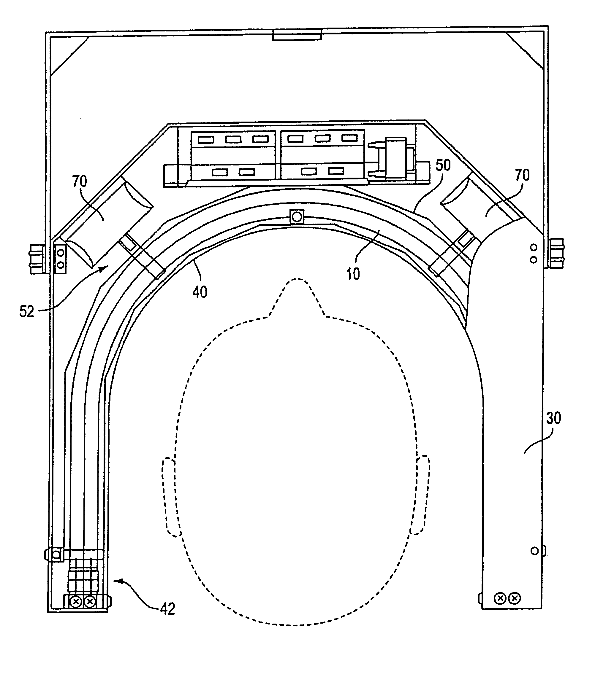
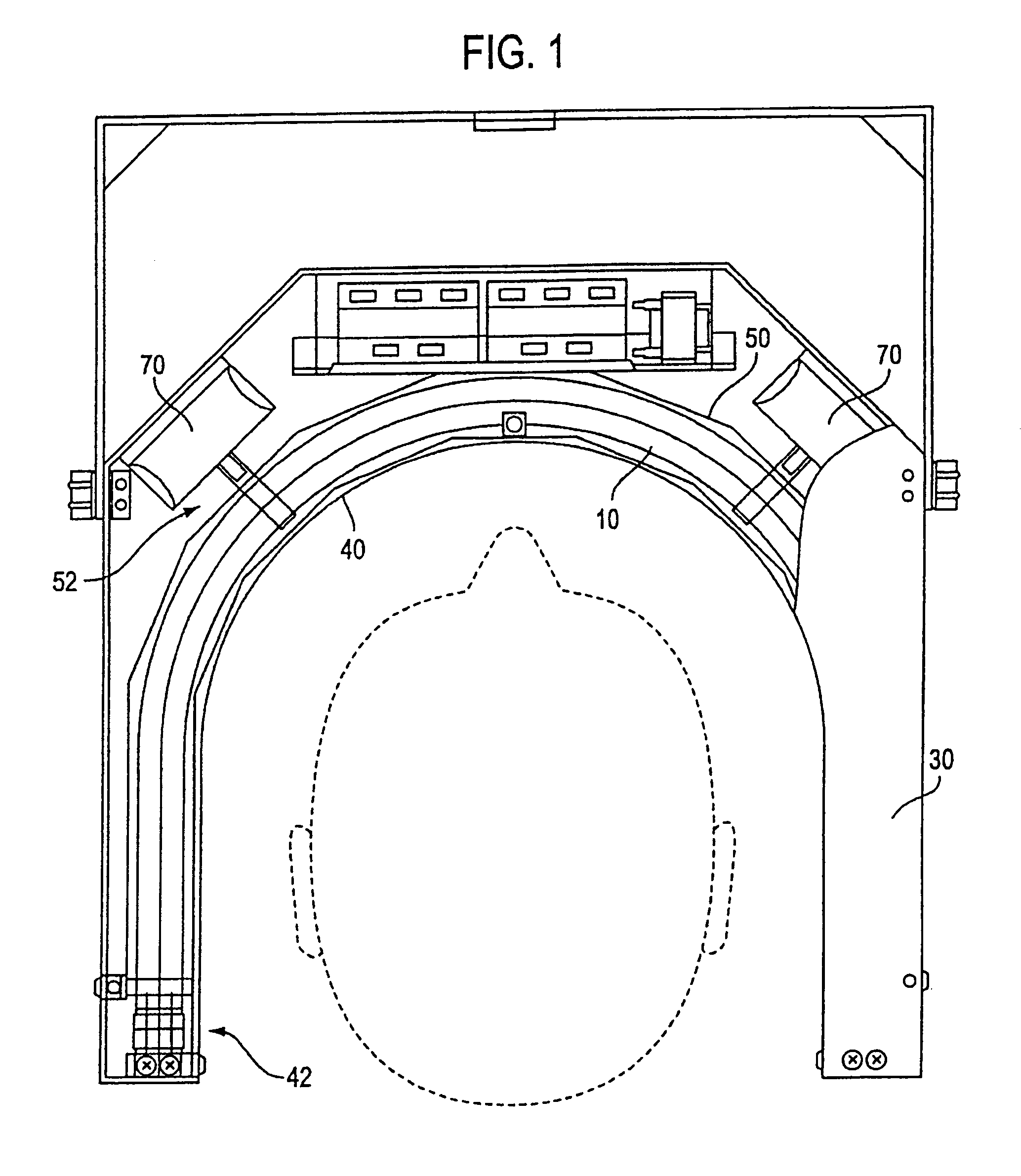
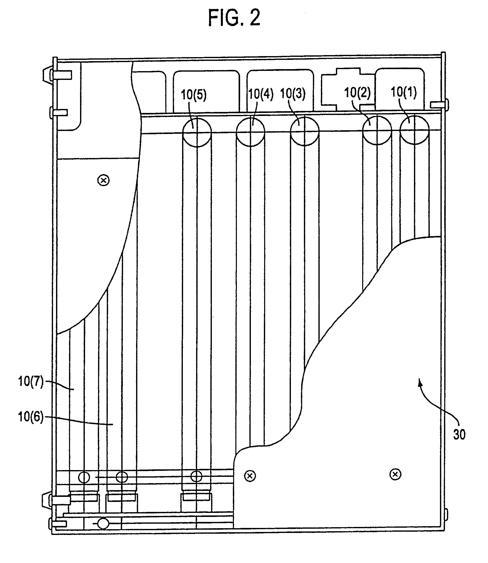
[0044]According to one preferred embodiment illustrated in FIGS. 1–8, seven U-shaped fluorescent tubes 10(1)–10(7) are driven by three electronic ballasts 20. Adjusting the ballast voltage controls the output power of the tubes. The tubes 10(1)–10(7) are supported by a housing 30 and are covered by a polycarbonate shield 40 which directs cooling airflow within the unit and prevents glass-patient contact in the event of tube breakage. An aluminum reflector 50 located behind the tubes increases both the output irradiance and the uniformity of the output distribution. The overall dimensions of the unit are approximately 38 cm H×45 cm W×44.5 cm D. FIG. 1 shows the position of the patient's head and nose.

Exemplary Light Sources

[0045]According to a preferred embodiment of the present invention, seven 36″ U-shaped F34T8 Ultra Blue fluorescent tubes 10(1)–10(7) provide a maximum visible light-emitting area 36 cm high by 46 cm wide (approximately 2850 cm2), with a minimum therapeutic...


PUM


Abstract

An apparatus and method for photodynamic therapy or photodynamic diagnosis using an illuminator comprising a plurality of light sources generally conforming to a contoured surface and irradiating the contoured surface with substantially uniform intensity visible light. The light sources may comprise generally U-shaped fluorescent tubes that are driven by electronic ballasts. Adjustment of the ballast voltage controls the output power of the tubes. The tubes are supported by a sheet-metal or plastic housing and are covered by a polycarbonate shield which directs cooling airflow within the unit and prevents glass-patient contact in the event of tube breakage. An aluminum reflector located behind the tubes increases both the output irradiance and the uniformity of the output distribution. The spacing of the U-shaped tubes is varied to increase the output at the edges of the illuminator to make the output more uniform. Also, different portions of the tubes are cooled at different amounts, to improve uniformity. A light sensor monitors output from the U-shaped tubes to provide a signal for adjusting the output from the tubes.

Description

[0001]The present application is a divisional of U.S. application Ser. No. 09 / 774,084, filed Jan. 31, 2001 now U.S. Pat. No. 6,709,446, which is a divisional of U.S. application Ser. No. 09 / 070,772, filed May 1, 1998 and now U.S. Pat. No. 6,223,071, the entire contents of which are incorporated herein by reference.BACKGROUND OF THE INVENTION[0002]1. Field of the Invention[0003]The present invention is directed to photodynamic therapy using an illuminator that provides a uniform distribution of visible light. In particular, the present invention is directed to an apparatus and method for photodynamic treatment (PDT) or diagnosis (PD) of actinic keratosis of the scalp or facial areas of a patient. The present invention is also directed to an apparatus and method for PDT and PD of other indications (e.g., acne) and other areas of the patient (e.g., arms, legs, etc.).[0004]As they are used here, the term “visible light” refers to radiant energy in the visible range of the electromagneti...

Claims


Application Information

Patent Timeline
IPC IPC(8): H01J61/44A61B5/00A61B6/00A61B17/00A61NA61N1/00A61N5/06C09K11/77
CPCA61N5/062A61N5/0617A61B5/0071A61N5/0616A61B2017/00057A61N2005/0642A61N2005/0655
Inventor LUNDAHL, SCOTTKOZODOY, REBECCACARROLL, RONALDLEPPELMEIER, ELTON
Owner DUSA PHARMA INC
Learn More