Two-mode photonic crystal fiber and applications thereof

a technology of photonic crystal fibers and optical fibers, applied in the direction of optical waveguide light guides, dual-mode fibers, instruments, etc., can solve the problems of increasing the complexity of the fiber design and fabrication process, and the conventional fibers generally only support two-mode operation in a very limited wavelength range, so as to achieve a wide operating wavelength range

Inactive Publication Date: 2007-03-13
THE HONG KONG POLYTECHNIC UNIV
View PDF6 Cites 27 Cited by
  • Summary
  • Abstract
  • Description
  • Claims
  • Application Information

AI Technical Summary

Benefits of technology

[0046]a generator, coupled to the fiber such that the transducer produces a flexural wave which propagates in the fiber, the flexural wave having a frequency, a propagation velocity and a wavelength, the wavelength of the flexural wave being a function of the frequency and the propagation velocity, and the wavelength of the flexural wave being selected to cause coupling of light from one of the fundamental and second order modes to the other of the fundamental and second order modes at a pre-selected wavelength, in which the wavelength of the flexural wave matches a modal beat length between the fundamental and second order modes, and thereby to generate light signals of the pre-selected wavelength in the other of the fundamental and second order modes at the output of the photonic crystal fiber.
[0055]a generator, coupled to the fiber such that the transducer produces a flexural wave which propagates in the fiber, the flexural wave having a frequency, a propagation velocity and a wavelength, the wavelength of the flexural wave being a function of the frequency and the propagation velocity, and the wavelength of the flexural wave being selected to cause coupling of light from one of the fundamental and second order modes to the other of the fundamental and second order modes at a pre-selected wavelength, in which the wavelength of the flexural wave matches a modal beat length between the fundamental and second order modes, and thereby to generate light signals of the pre-selected wavelength in the other of the fundamental and second order modes at the output of the photonic crystal fiber.
[0061]a generator, coupled to the fiber such that the transducer produces a flexural wave which propagates in the fiber, the flexural wave having a frequency, a propagation velocity and a wavelength, the wavelength of the flexural wave being a function of the frequency and the propagation velocity, and the wavelength of the flexural wave being selected to cause coupling of light from one of the fundamental and second order modes to the other of the fundamental and second order modes at a pre-selected wavelength, in which the wavelength of the flexural wave matches a modal beat length between the fundamental and second order modes, and thereby to generate light signals of the pre-selected wavelength in the other of the fundamental and second order modes at the output of the photonic crystal fiber.

Problems solved by technology

However, disadvantages exist with the two-mode devices using conventional circular or elliptical core fibers in that these conventional fibers generally only support two-mode operation in a very limited wavelength range.
This inevitably increases the complexity of the fiber design and fabrication process.

Method used


Image

  • Two-mode photonic crystal fiber and applications thereof
  • Two-mode photonic crystal fiber and applications thereof
  • Two-mode photonic crystal fiber and applications thereof

Examples


Embodiment Construction

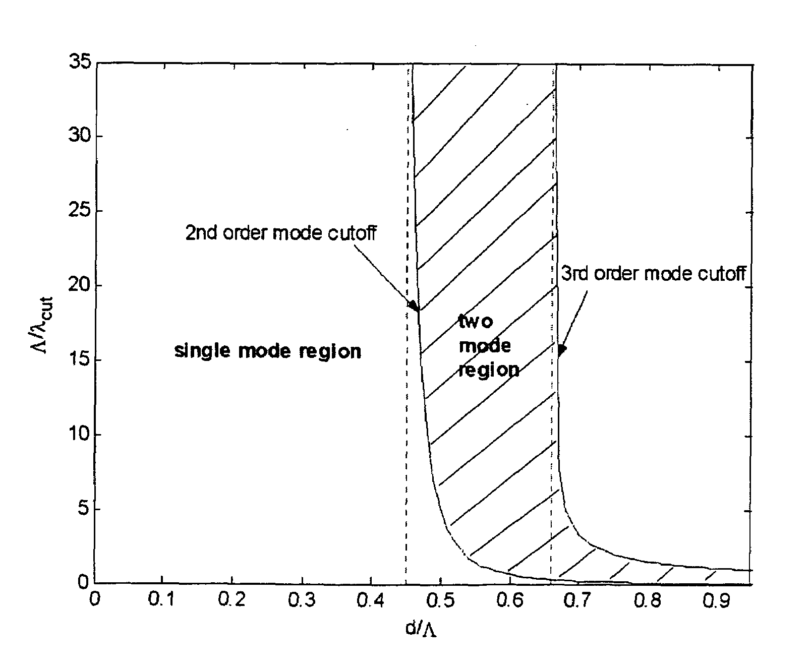
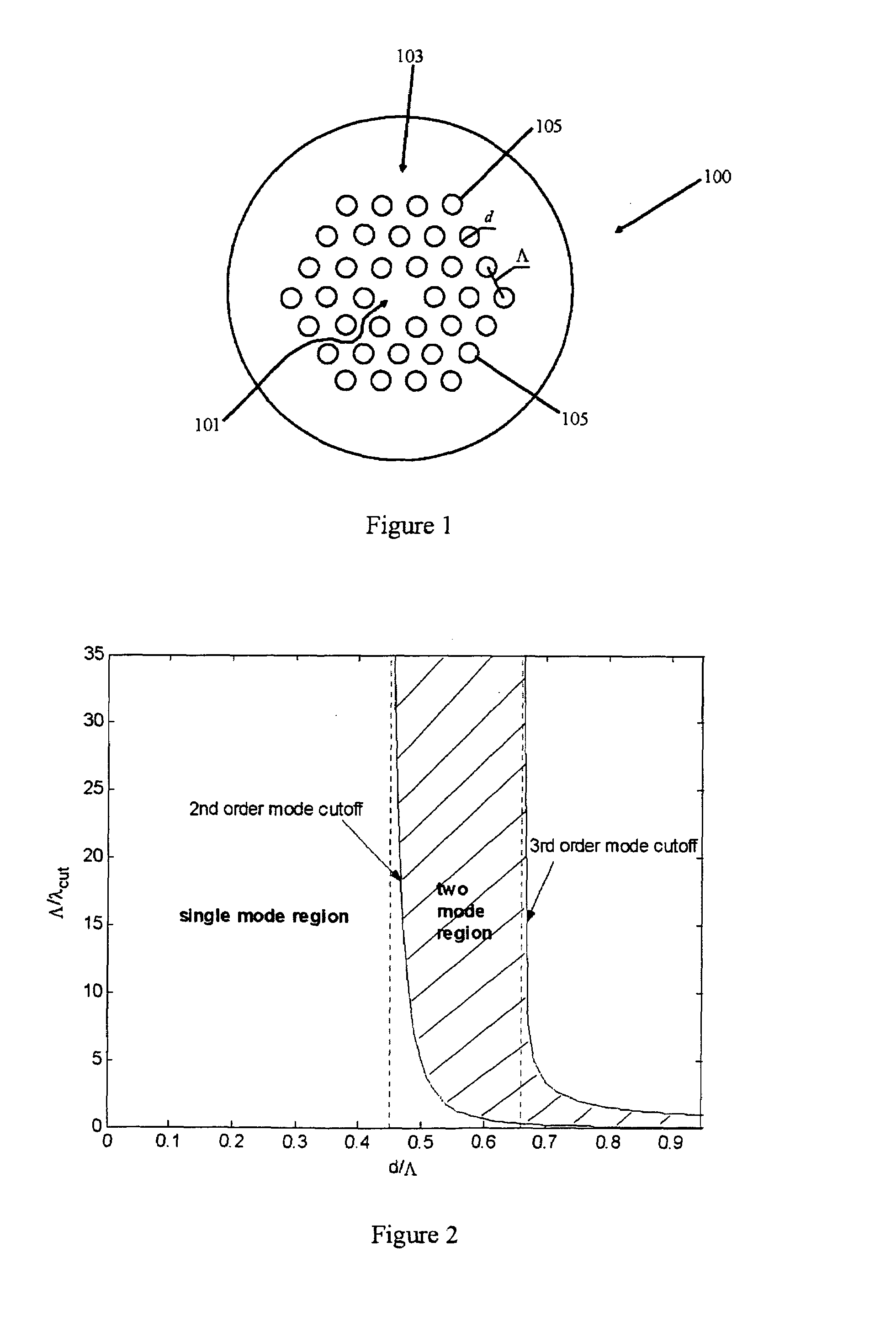
[0087]FIG. 1 illustrates an index-guiding photonic crystal optical fiber 100 (hereinafter PCF). The PCF can be fabricated by stacking silica capillaries periodically in a hexagonal close packed array and replacing the central capillary with a solid silica rod of the same outer dimensions as generally understood in the art. The PCF 100 has a solid core 101 of a substantially transparent core material, having a core refractive index, n, and a length, l, and having a core diameter, of preferably at least 3 μm. The PCF 100 further includes a cladding region 103 surrounding the length of core material. The cladding region includes a first substantially transparent cladding material, having a first refractive index, and the first substantially transparent cladding material has embedded along its length a substantially periodic array of holes 105, having a diameter, d, and being spaced apart by a pitch, Λ. The holes 105 have a second refractive index, which is less than the first refractiv...


PUM

PropertyMeasurementUnit
diameteraaaaaaaaaa
wavelengthsaaaaaaaaaa

Abstract

A two-mode photonic crystal fiber includes a core of a substantially transparent core material. The core material has a core refractive index and a length, and has a core diameter. The fiber also includes a cladding region surrounding the length of core material. The cladding region has a first substantially transparent cladding material, having a first refractive index. The first substantially transparent cladding material has embedded along its length a substantially periodic array of holes, having a diameter, d, and being spaced apart by a pitch, Λ. The holes have a second refractive index, which is less than the first refractive index. The dimensions of the hole diameter, d, and the pitch, Λ, co-operate to give two modes propagation within the photonic crystal fiber independent of input radiation wavelength for any value of the pitch, Λ, for a substantially fixed d / Λ ratio within a range of approximately 0.45–0.65.

Description

BACKGROUND[0001]1. Field of the Invention[0002]The present invention relates generally to two-mode photonic crystal optical fiber structures and to applications thereof.[0003]2. Background of the Invention[0004]Two-mode optical fibers have wide applications such as mode converters, mode selective couplers, acousto-optic frequency shifters, acoustic-optic tunable filters, wavelength tunable optical switches, add-drop multiplexers and interferometric fiber sensors, and so on. There generally exists a cut-off wavelength in a conventional circularly symmetric single mode step index fiber. For an appropriate operating wavelength below the cut-off wavelength, two-mode operation can be achieved in such a conventional single-mode fiber. In addition, U.S. Pat. No. 4,832,437, entitled “Fiber Optic Inter-Mode Coupling Single Side Band Frequency Shifter” and issued on May 23, 1989, and U.S. Pat. No. 4,915,468, entitled “Apparatus Using Two-Mode Optical Waveguide with Non-Circular Core” and issu...

Claims


Application Information

Patent Timeline
Patent Type & Authority Patents(United States)
IPC IPC(8): G02B6/32
CPCG02B6/02047G02B6/02357G02B6/02347G02B6/0239
Inventor JIN, WEIJU, JIANWANG, ZHI
Owner THE HONG KONG POLYTECHNIC UNIV
Why Eureka
Try Eureka