
Electromotive adjustment device

a technology of adjusting device and motor, which is applied in the direction of dynamo-electric machines, toothed gearings, portable lifting, etc., can solve the problems of drive motor wear and prohibitive installation, and achieve the effect of further reducing the number of components

Inactive Publication Date: 2007-03-20
ELODRIVE STELLANTRIEBSTECHN
View PDF19 Cites 27 Cited by
  • Summary
  • Abstract
  • Description
  • Claims
  • Application Information

AI Technical Summary

Benefits of technology

"The present invention is an electromotive adjustment device that includes a housing, a gear mechanism, and a drive motor. The use of a brushless drive motor allows for a more wear-resistant and unlimited service life. The gear mechanism includes intermeshing gear wheels to define a drive train, and the output journal has a tooth portion in engagement with a helical spur gear of the gear mechanism. The output journal can have multiple teeth, and the gear wheels can have oblique teeth. The gear mechanism can have at least two gear stages for reducing motor speed, and the gear wheels can be supported by a common carrier. The housing may be constructed with thin walls and an operative drive unit may not require a housing. A spring element can be provided for shifting the control element, and the housing can be comprised of two housing portions. The drive motor has an attachment flange that eliminates the need for additional fasteners. The adjustment device becomes small and compact."

Problems solved by technology

There may, however, also be situations which require movement of the control element into different positions at short intervals in response to a change in temperature.
Drive motors of this type generate sparks during startup, thereby progressively wearing off the drive motor.
As the installation space is relatively small, the use of conventional adjustment devices caused problems that even render their installation prohibitive.

Method used


Image

  • Electromotive adjustment device
  • Electromotive adjustment device
  • Electromotive adjustment device

Examples


Embodiment Construction

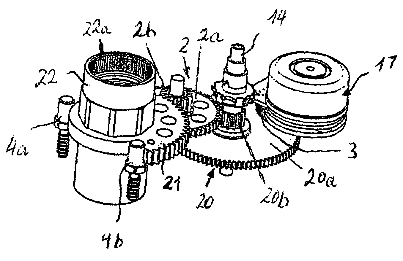
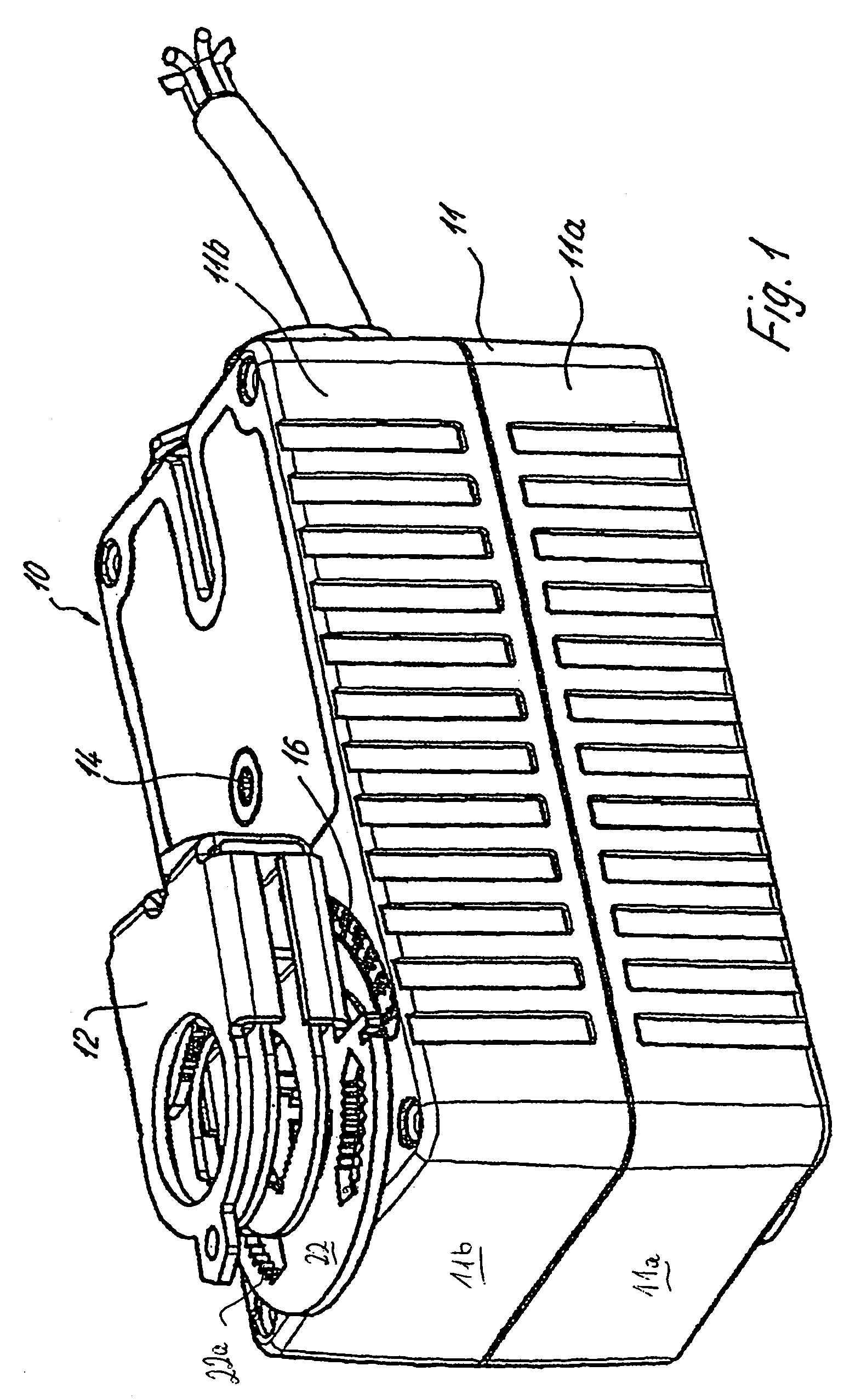
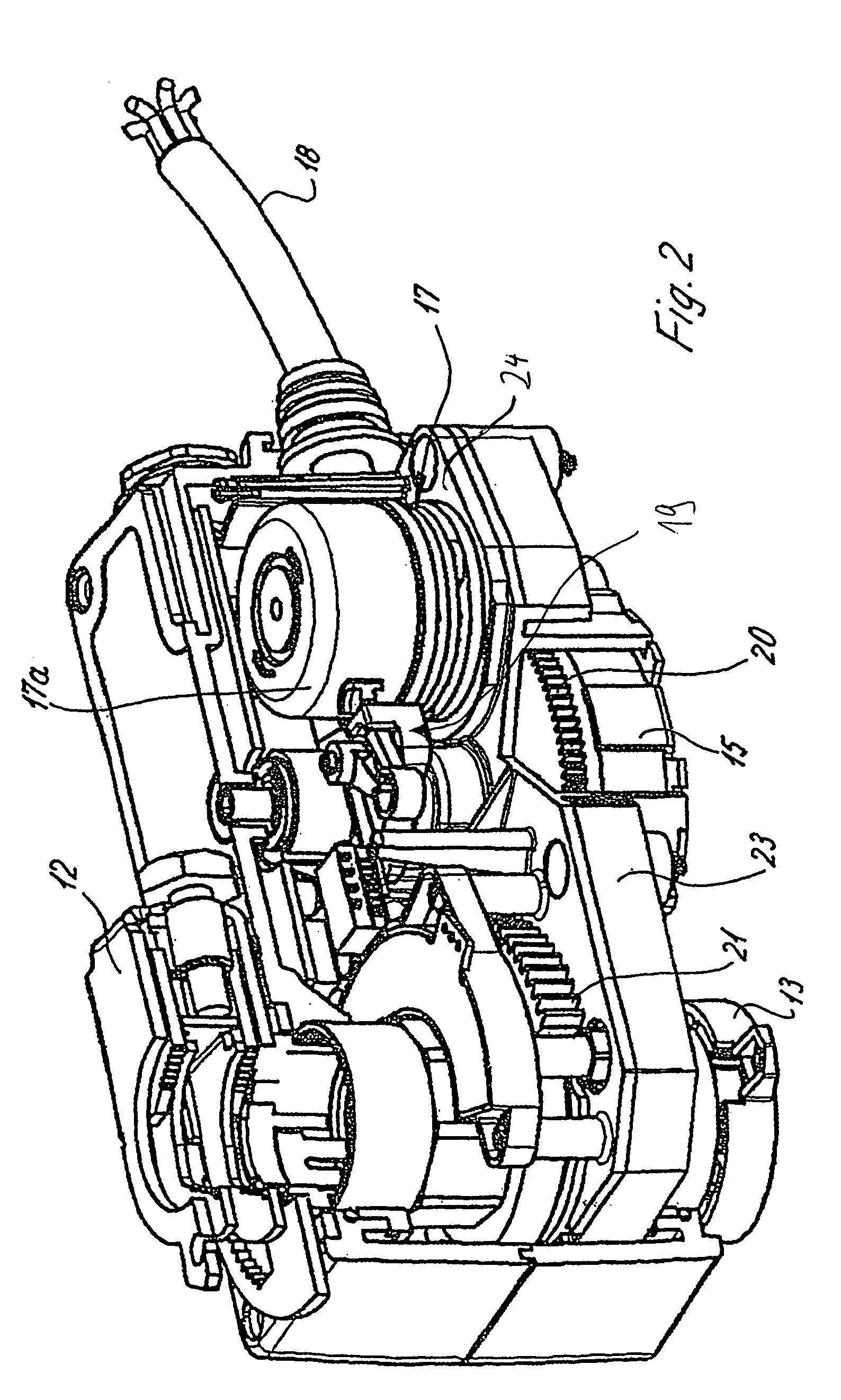
[0023]Throughout all the Figures, same or corresponding elements are generally indicated by same reference numerals. These depicted embodiments are to be understood as illustrative of the invention and not as limiting in any way. It should also be understood that the drawings are not necessarily to scale and that the embodiments are sometimes illustrated by graphic symbols, phantom lines, diagrammatic representations and fragmentary views. In certain instances, details which are not necessary for an understanding of the present invention or which render other details difficult to perceive may have been omitted.

[0024]This is one of four applications all filed on the same day. These applications deal with related inventions. They are commonly owned and have same inventive entity. These applications are unique, but incorporate the other by reference. Accordingly, the following U.S. patent applications are hereby expressly incorporated by reference: “Adjustment Device”, “Adjustment Driv...


PUM


Abstract

An electromotive adjustment device for adjusting a control element includes a housing and a gear mechanism which has a plurality of intermeshing gear wheels to define a drive train. In driving relationship with the gear mechanism is a drive motor which is constructed as a brushless motor with an external rotor and includes an output journal, whereby the output journal has a tooth portion in engagement with a helical spur gear wheel of the gear mechanism.

Description

CROSS-REFERENCES TO RELATED APPLICATIONS[0001]This application is a continuation of prior filed copending PCT International application no. PCT / EP02 / 03837, filed Apr. 6, 2002, on which priority is claimed under 35 U.S.C. §120, the disclosure of which is hereby incorporated by reference.[0002]This application claims the priority of German Patent Application, Serial No. DE 201 07 326.9, filed Apr. 27, 2001, pursuant to 35 U.S.C. 119(a)-(d), the disclosure of which is incorporated herein by reference.BACKGROUND OF THE INVENTION[0003]The present invention relates to an electromotive adjustment device, in particular for use with adjustable flap valves.[0004]An electromotive adjustment device of a type involved here finds application especially in heating, air-conditioning and ventilation systems for opening and closing a control element of a flap valve. The respective adjusting movement depends hereby on the intended purpose. For example, in case of fire, it may be necessary to open or c...

Claims


Application Information

Patent Timeline
Patent Type & Authority Patents(United States)
IPC IPC(8): H02K7/116F16K31/04F16H1/02F16H1/20F16H37/04F16H55/17F16H57/02F16K31/53
CPCH02K7/116F16H1/20F16H57/02Y10T74/19684Y10T74/19651Y10T74/19642Y10T74/19647
Inventor SCHUNKE, KURTBUCHHOLZ, BERNDPALM, DIETERBRUNS, GERHARD
Owner ELODRIVE STELLANTRIEBSTECHN
Learn More