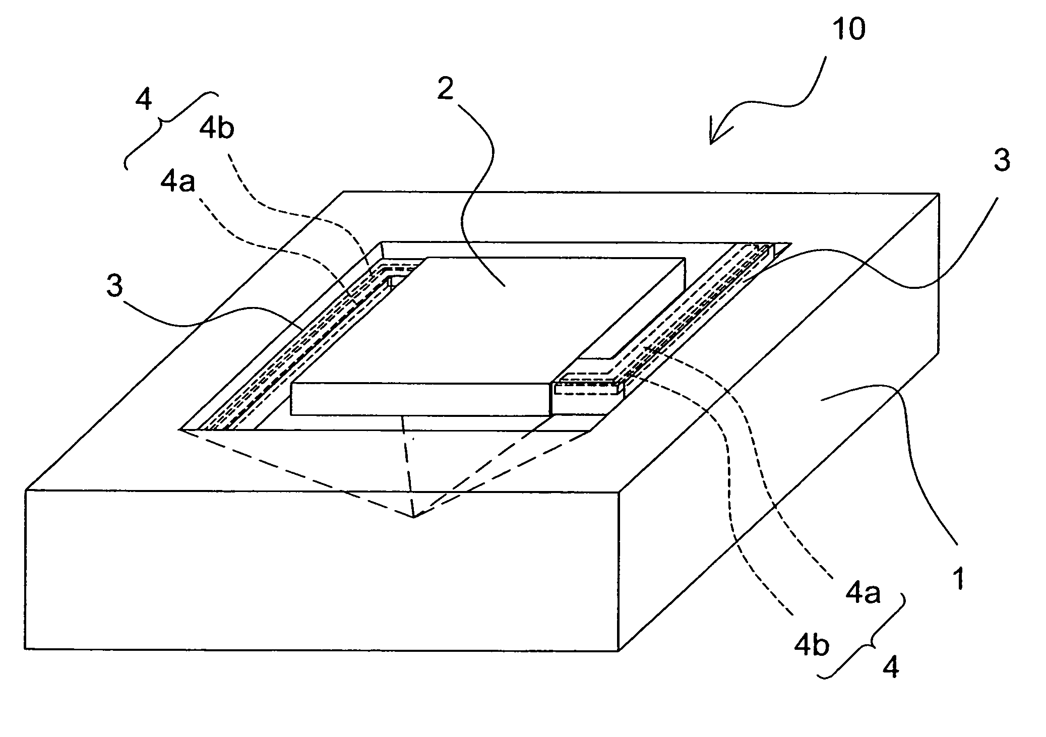
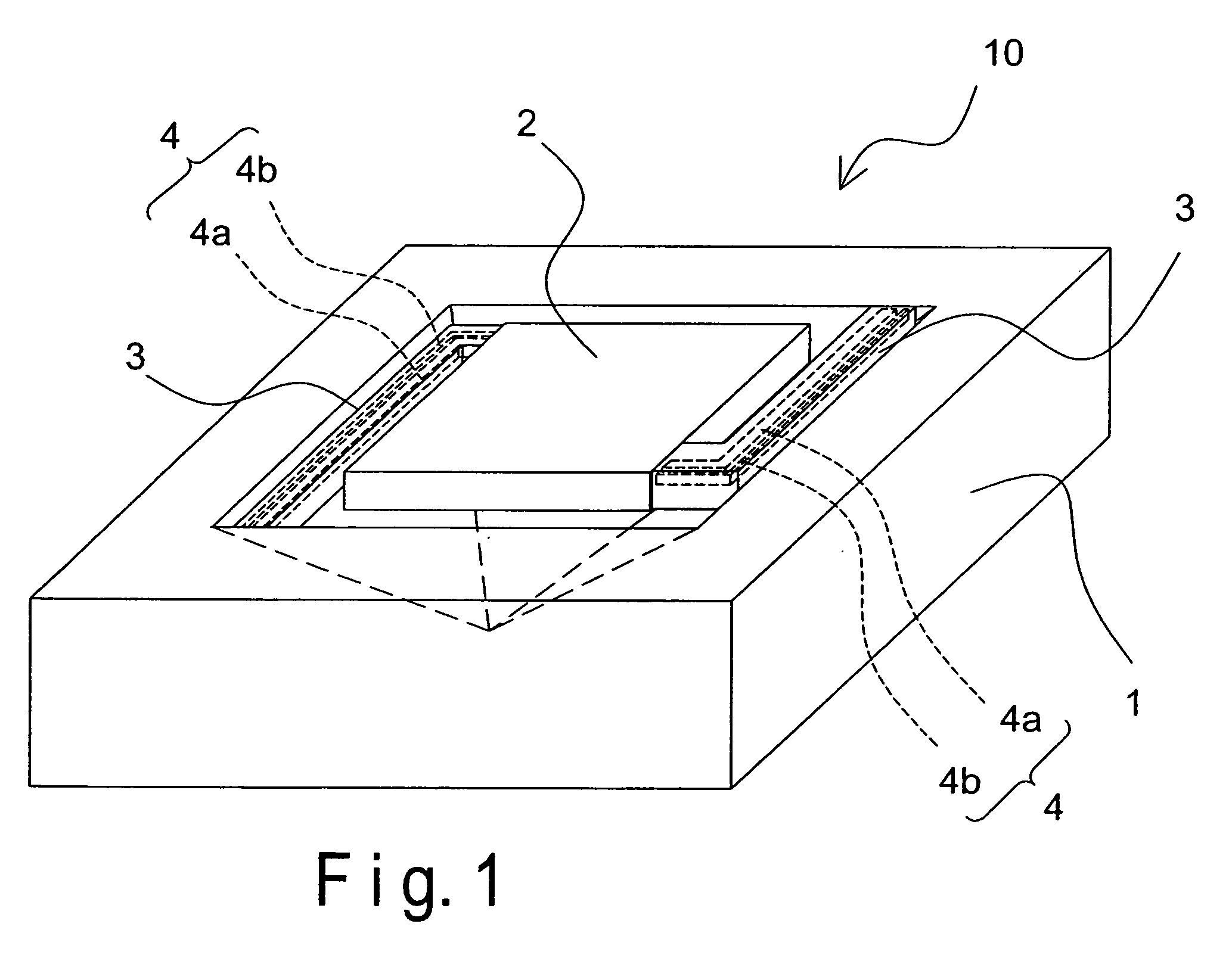
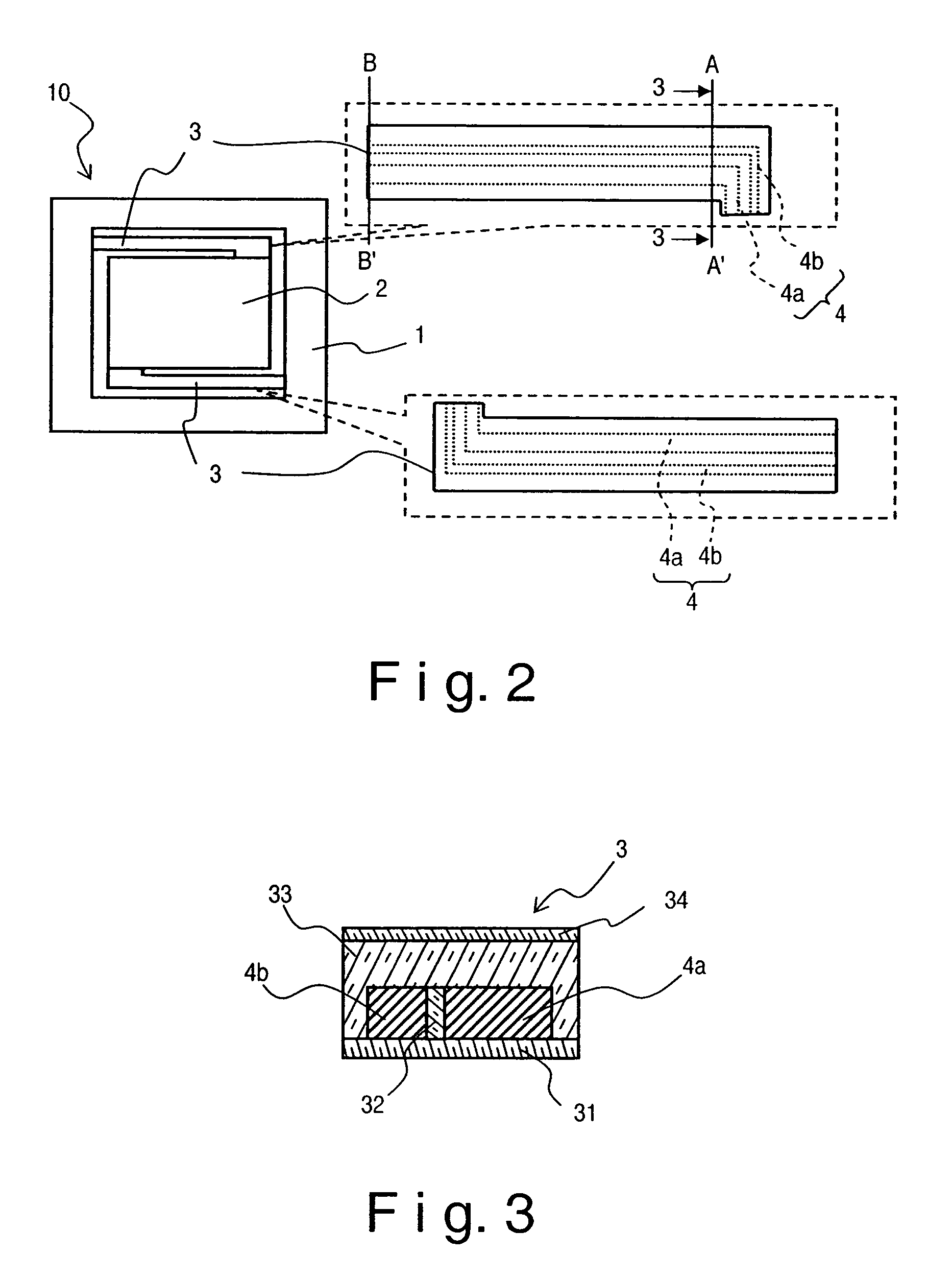
Infrared radiation detecting device
a technology of infrared radiation and detection device, which is applied in the direction of optical radiation measurement, instruments, material analysis, etc., can solve the problems of insufficient increase in thermal noise, and breakage so as to improve the structural rigidity of the support beam, increase the structural stability or mechanical strength and reduce the thermal noise of infrared radiation detection device
- Summary
- Abstract
- Description
- Claims
- Application Information
AI Technical Summary
Benefits of technology
Problems solved by technology
Method used
Image
Examples
second embodiment
[0055]Referring now to FIGS. 7–10, modifications to the infrared radiation detecting device 10 will now be explained in accordance with a second embodiment. In particular, a pair of modified infrared radiation detecting devices 110 and 110′ will now be explained in which the cross-sectional dimensions of the polysilicon films have been modified. In view of the similarity between the first and second embodiments, the parts of the second embodiment that are identical to the parts of the first embodiment will be given the same reference numerals as the parts of the first embodiment. Moreover, the descriptions of the parts of the second embodiment that are identical to the parts of the first embodiment may be omitted for the sake of brevity.
[0056]The infrared radiation detecting device 110 of the second embodiment is basically identical to the infrared radiation detecting device 10 of the first embodiment, except that in the second embodiment the cross sectional area of a p-type polysil...
third embodiment
[0058]Referring now to FIGS. 11 to 13, an infrared radiation detecting device 210 in accordance with a third embodiment will now be explained. In view of the similarity between the first and third embodiments, the parts of the third embodiment that are identical to the parts of the first embodiment will be given the same reference numerals as the parts of the first embodiment. Moreover, the descriptions of the parts of the third embodiment that are identical to the parts of the first embodiment may be omitted for the sake of brevity.
[0059]The infrared radiation detecting device 210 of the third embodiment of the present invention is basically identical to the infrared radiation detecting device 10 of the first embodiment, except for a structure of a pair of polysilicon films 204a and 204b of a thermopile 204 disposed on each of the support beams 203. The cross-sectional dimensions of the polysilicon films 204a and 204b of the thermopile 204 disposed on each of the support beams 203 ...
fourth embodiment
[0066]Referring now to FIG. 14, an infrared radiation detecting device 310 in accordance with a fourth embodiment will now be explained. In view of the similarity between the third and fourth embodiments, the parts of the fourth embodiment that are identical to the parts of the third embodiment will be given the same reference numerals as the parts of the third embodiment. Moreover, the descriptions of the parts of the fourth embodiment that are identical to the parts of the third embodiment may be omitted for the sake of brevity.
[0067]The infrared radiation detecting device 310 of the fourth embodiment is basically identical to the infrared radiation detecting device 210 of the third embodiment, except for an arrangement of a pair of a p-type polysilicon film 304a and an n-type polysilicon film 304b of a thermopile 304 disposed on each of the support beams 303. The cross-sectional dimensions of the polysilicon films 304a and 304b of the thermopile 304 disposed on each of the suppor...
PUM
 Abstract
Description
Claims
Application Information
 - R&D
- Intellectual Property
- Life Sciences
- Materials
- Tech Scout
- Unparalleled Data Quality
- Higher Quality Content
- 60% Fewer Hallucinations
Browse by: Latest US Patents, China's latest patents, Technical Efficacy Thesaurus, Application Domain, Technology Topic, Popular Technical Reports.
© 2025 PatSnap. All rights reserved.Legal|Privacy policy|Modern Slavery Act Transparency Statement|Sitemap|About US| Contact US: help@patsnap.com


