Instrument cluster with laser beam illumination

a laser beam and instrument cluster technology, applied in the field of analog displays, can solve the problems of increasing the difficulty of attaching cables, wires and other devices to the back, difficult calibration and maintenance of all meter movements, etc., and achieves the effect of easy fabrication, easy calibration and simple construction

Inactive Publication Date: 2007-03-20
YAZAKI NORTH AMERICA
View PDF17 Cites 21 Cited by
  • Summary
  • Abstract
  • Description
  • Claims
  • Application Information

AI Technical Summary

Benefits of technology

[0005]The present invention provides analog displays suitable for automotive instrument clusters and the like which displays are simple in construction, easy to fabricate in single or multiple display field configurations, easily calibrated and require no conventional meter movements. In general, this is accomplished in a system including at least one display field across which values of a measured quantity are represented in an analog fashion, a pulsed light source capable of producing a light beam, a means for causing the light beam to repeatedly pass across the display field, and a controller responsive to the measured quantity to turn the light source on where the location of the beam relative to the sides of the display field corresponds to the current value of the measured quantity. In this context, an “analog” display is one in which the positions of a marker within a display field having physical boundaries represent data values.
[0008]In the preferred form, means are provided for calibrating the light beam sweep to a “zero” position at the beginning of each pass thereby eliminating the tendency for position / timing errors to accumulate in the system and cause false indications of the measured quantities in the display fields.
[0009]The display fields are arcuate in the described embodiments, but this is by way of illustration only. The display fields may be arranged in tiers or horizontal rows and the beam caused to move sequentially across and between the rows by means of a multi-faceted rotating mirror the reflective surfaces of which produce different angles of incidence between the light beam and the receiver surface of the display system within which the display field or fields are defined. The preferred form of the light source is a pulsed diode laser which can be turned on and off at precisely selected times to produce a high degree of resolution in the display fields; e.g., resolutions of 0.1 degrees per pulse in the beam sweep are readily obtained. The mirror is rotated fast enough to make at least 30 to 50 full passes across the display fields each second thereby creating the appearance of a continuous light marker in each field at the analog value position.

Problems solved by technology

It has become increasingly more difficult to attach cables, wires and other devices to the back side of the instrument cluster to provide all of the various desirable displays while retaining flexibility and accessability.
Moreover, all of the meter movements are difficult to calibrate and to maintain in calibration.

Method used


Image

  • Instrument cluster with laser beam illumination
  • Instrument cluster with laser beam illumination
  • Instrument cluster with laser beam illumination

Examples


Embodiment Construction

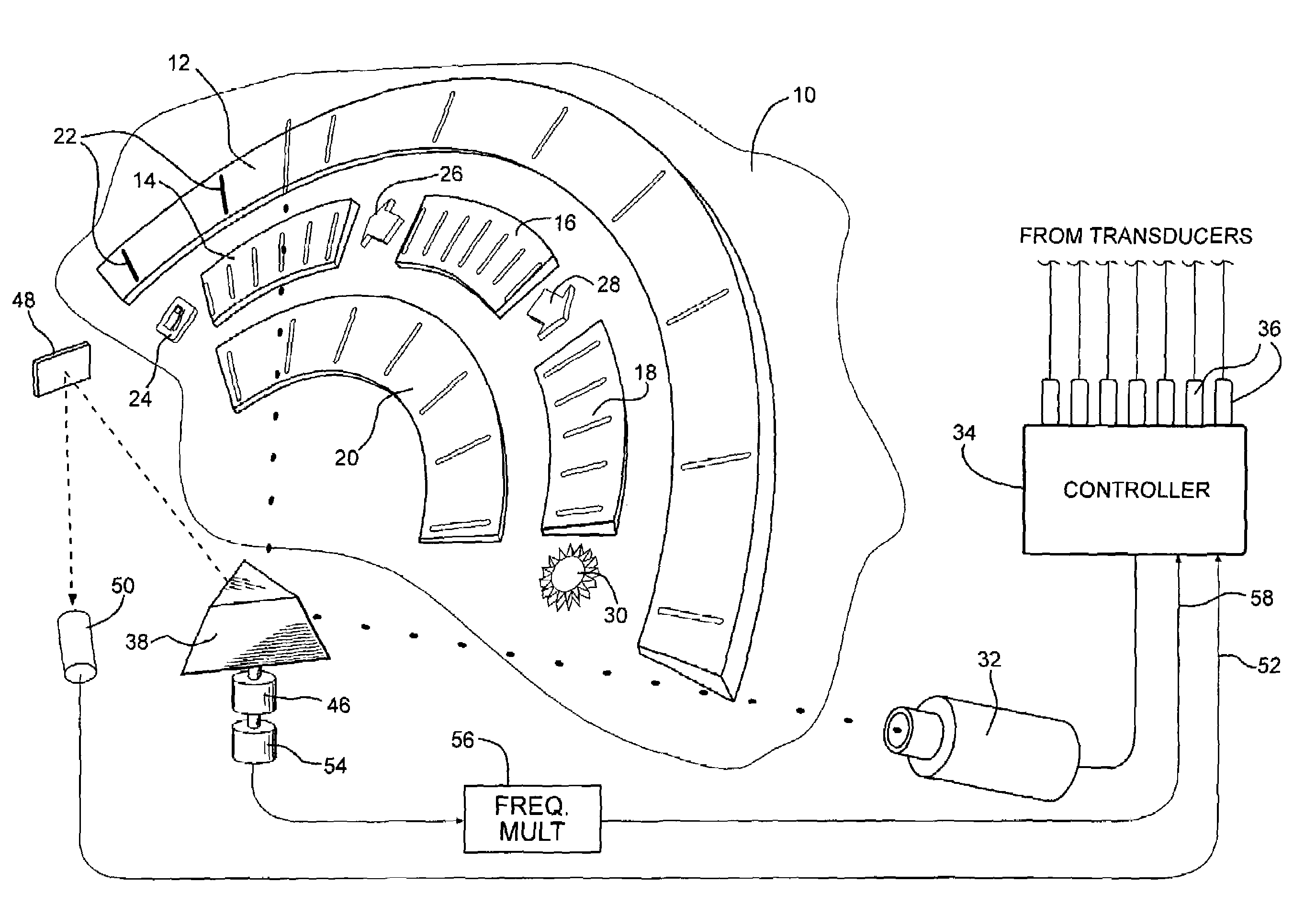
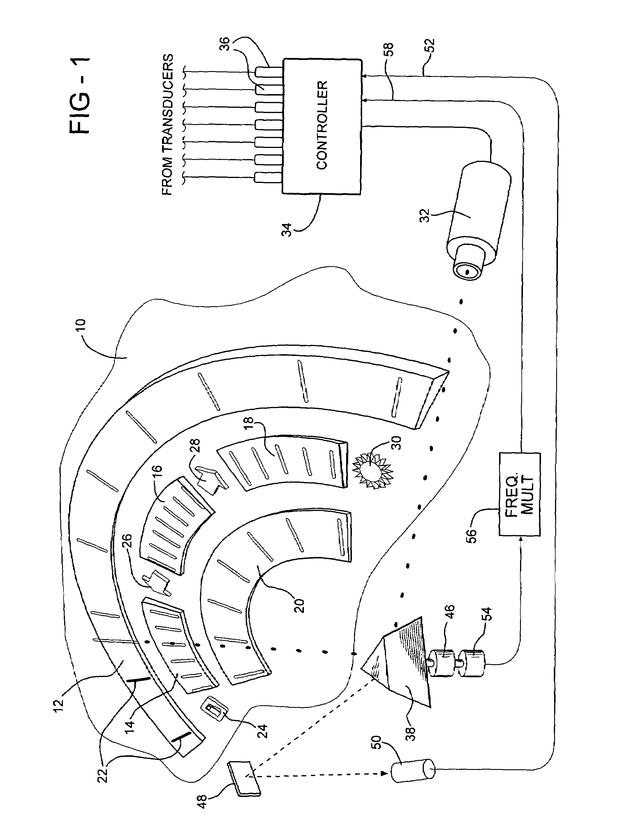
[0016]Referring to the figures, an automotive instrument cluster 10 in the form of a plastic fascia is shown in perspective to comprise a plurality of display fields 12, 14, 16, 18 and 20 arranged in three concentric tiers or horizontal rows. The outermost row is made up of the entirety of the large field display 12 and in this case may be taken to be representative of an automotive speedometer display with low values at the left end and higher values toward the rightmost or clockwise end. The middle row is made up of discreet display fields 14, 16 and 18 and may be taken to represent quantities such as coolant temperature, fuel level, oil pressure and the like. The innermost tier is made up of a single display field 20 which may be a tachyometric display of engine speed. Each tier is inclined relative to the cluster, the outermost tier having the greatest angle of inclination and the innermost tier having the smallest. All of the measured quantities mentioned above are by way of ex...


PUM


Abstract

An automotive instrument cluster containing a grouping of display fields representing measured automotive operating quantities such as speed, temperature and pressure. Illumination markers which are analogs of pointers are created within the display fields from a single beam-type light source by means of a multi-faceted rotating mirror and a controller which correlates measured signal quantities representing the vehicle operating quantities to mirror angle in turning the light source on so as to create an illumination marker at a strategic position within each of the display fields. The display is refreshed 50 times per second so as to create the appearance of a continuous marker in each of the display fields. Calibration is provided by means of a separate diode sensor.

Description

FIELD OF THE INVENTION[0001]This invention relates to analog displays for measured quantities such as automotive speed, coolant temperature, fuel level and the like, and more particularly to an instrument cluster comprising a plurality of display fields and having no conventional meter movements, pointers or other components susceptible to inertial effects.BACKGROUND OF THE INVENTION[0002]Automotive instrument clusters typically comprise large discreet display areas for a speedometer and a tachometer, and a number of smaller displays for coolant temperature, oil pressure, oil temperature, fuel level and the like. Arranged within and around the cluster are other indicators showing low fluid level conditions, turn signal operation, emergency light blinkers and so forth. The analog displays within the display fields are provided by means of devices having electromechanical movements for causing angular sweep of a needle across the display field. In American systems, low values of the m...

Claims


Application Information

Patent Timeline
Patent Type & Authority Patents(United States)
IPC IPC(8): G01B11/14B60Q1/00G09G3/00G09G5/00
CPCG01D13/22B60K37/02B60K2350/1064B60K2370/154
Inventor LI, KANG
Owner YAZAKI NORTH AMERICA
Why Eureka
Try Eureka