Seal ring and method of forming micro-topography ring surfaces with a laser

a technology of micro-topography and seal face, which is applied in the field of seal ring, can solve the problems of non-uniform depth of semi-circular groove along the lateral width, excessive depth of overlap between adjacent pairs of passes,

Inactive Publication Date: 2007-03-27
FLOWSERVE MANAGEMENT CO
View PDF47 Cites 37 Cited by
  • Summary
  • Abstract
  • Description
  • Claims
  • Application Information

AI Technical Summary

Problems solved by technology

While a rectangular shaped laser beam may be used to form the rectangular steps of the '317 patent, it has been found that when two adjacent passes of a laser beam overlap, the area of overlap between each adjacent pair of passes has an excessive depth since the overlap area is cut once on the first pass a

Method used


Image

  • Seal ring and method of forming micro-topography ring surfaces with a laser
  • Seal ring and method of forming micro-topography ring surfaces with a laser
  • Seal ring and method of forming micro-topography ring surfaces with a laser

Examples


Embodiment Construction

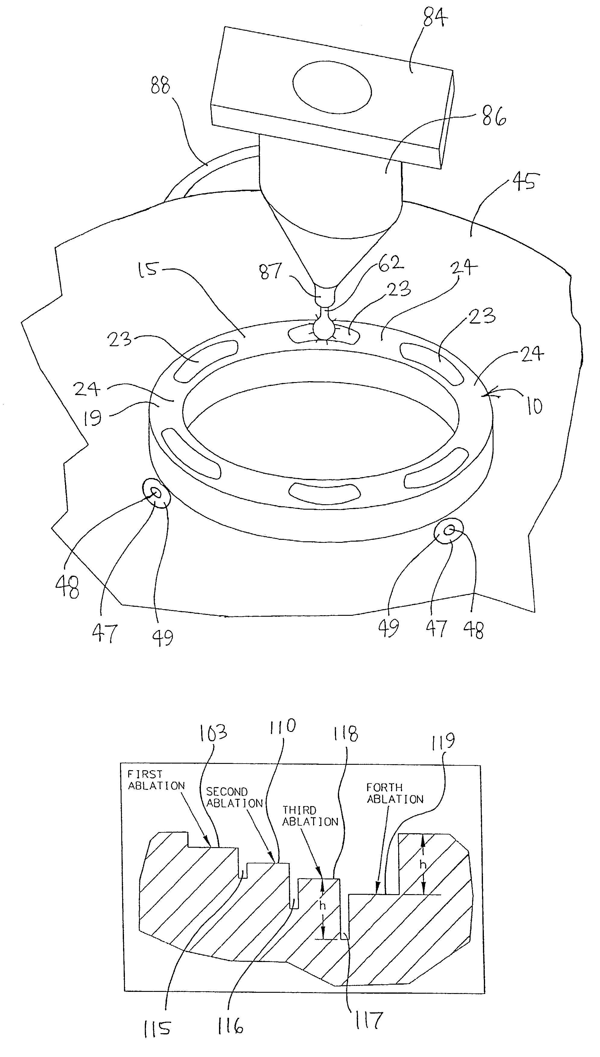
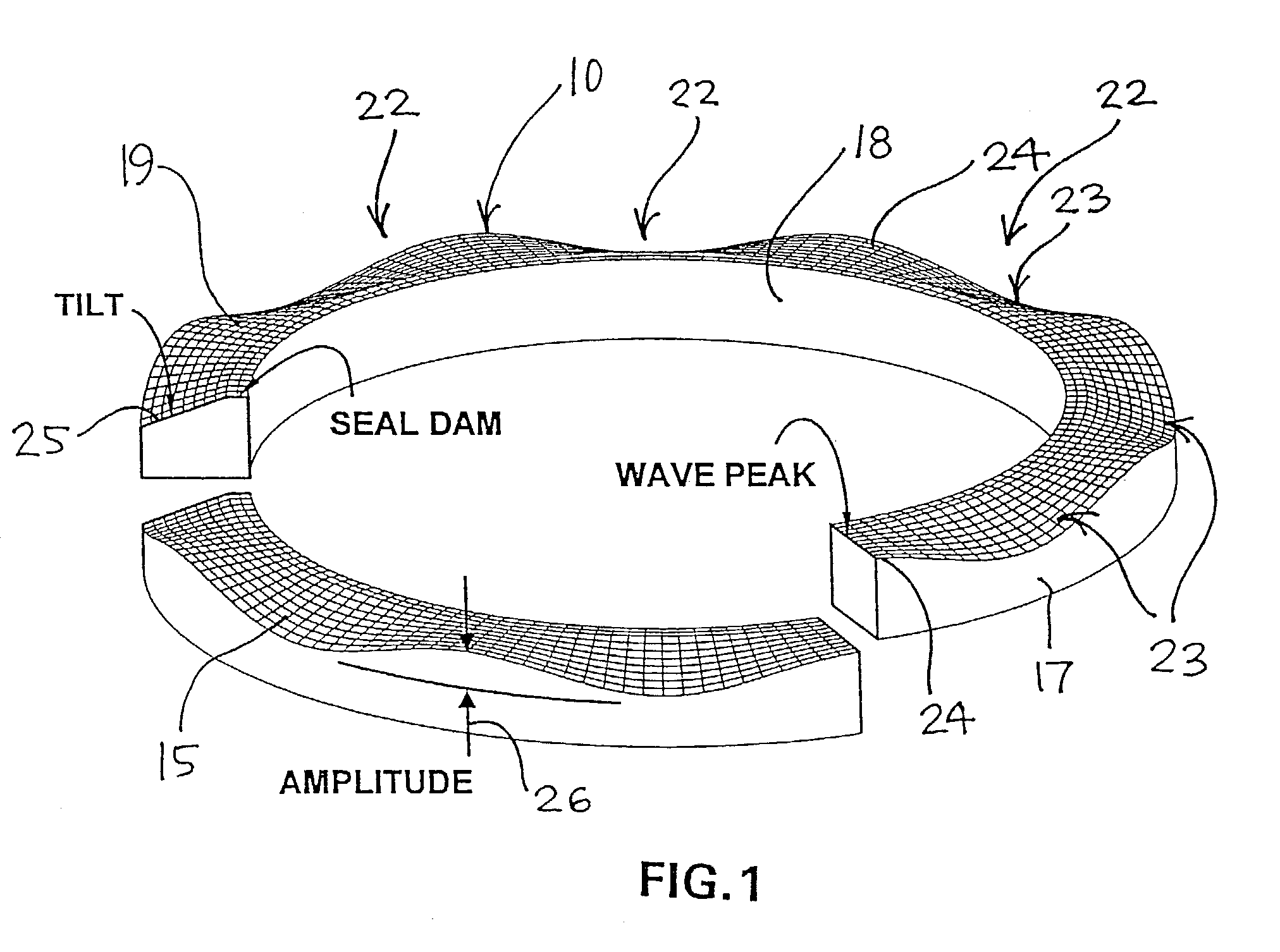
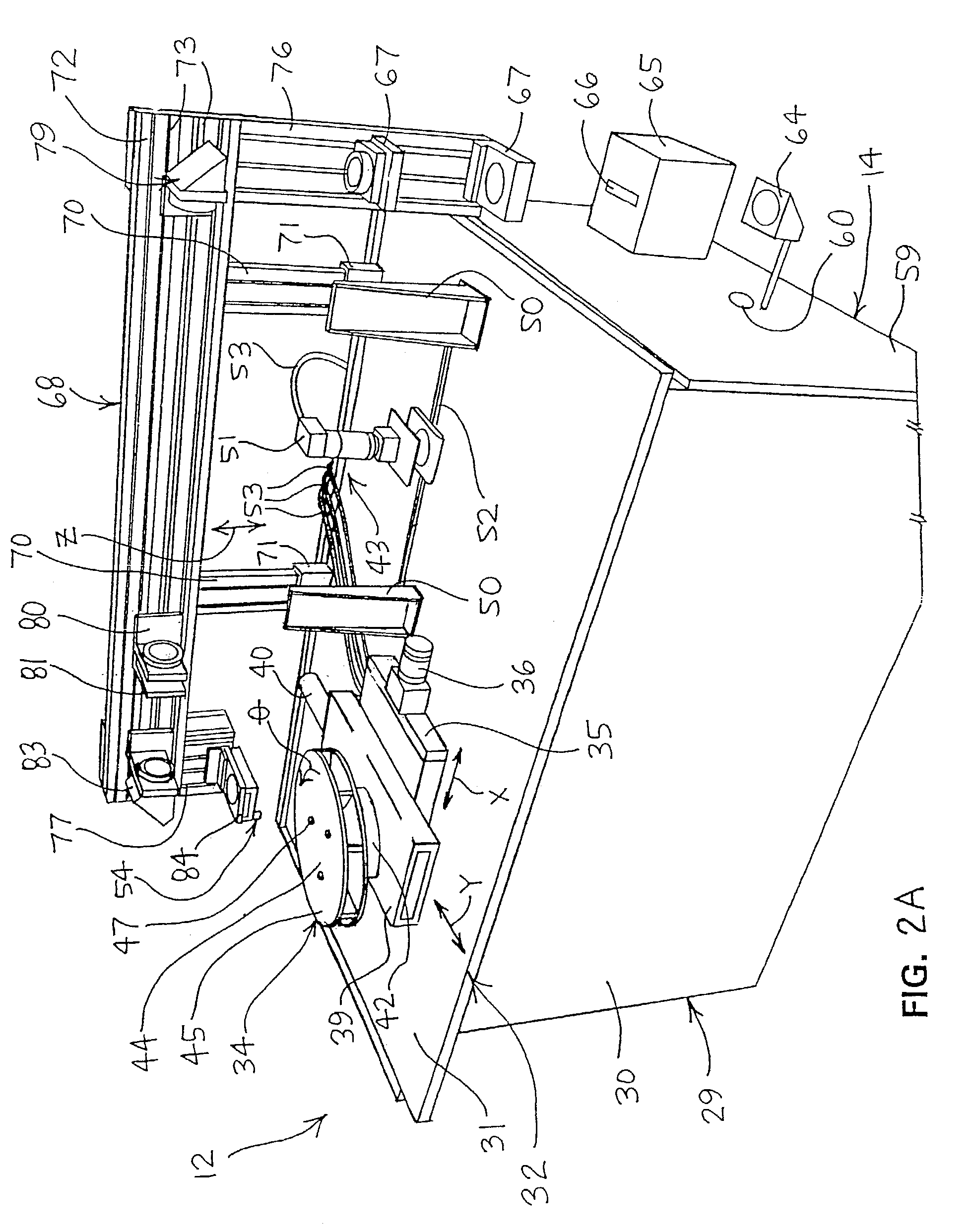
[0038]Referring to FIGS. 1, 2A and 2B, the invention relates to a seal ring 10 (FIG. 1) for a shaft seal and to seal ring machining equipment 12 which has a laser unit 14 that forms micro-topography depth features in the seal face 15 of the seal ring 10. As described in greater detail herein, the laser unit 14 generates a shaped laser beam which has non-linear edges at least on opposite sides of the beam to provide successive cuts in the seal face 15 wherein the cuts have a non-uniform depth across the lateral width thereof to permit beam overlap and more accurately and precisely define the micro-topography depth features.

[0039]With respect to the seal ring 10 of FIG. 1, the seal ring 10 is formed for use in a generally conventional manner in that the seal ring 10 has an annular shape defined by an outer diameter 17 and an inner diameter 18. The seal face 15 extends radially between the outer and inner diameters 17 and 18 and defines a sealing region 19 which extends radially thereb...


PUM

PropertyMeasurementUnit
Shapeaaaaaaaaaa
Depthaaaaaaaaaa
Nonlinear systemaaaaaaaaaa

Abstract

A seal ring of a shaft seal has micro-topography depth features, such as wavy faces or radial grooves, formed in the seal face which define a hydrodynamic seal region between opposing seal faces. The micro-topography depth features are formed by an excimer laser shaped such that the beam shape at least has non-linear side edges which define convergent side areas of the beam. The convergent side areas are defined by side edge sections which converge toward each other and preferably are non-linear. For example, the beam shape may be circular or elliptical. The laser beam first cuts repeatedly along the same beam path to define a cut with an increasing depth, whereby the laser beam is shifted incrementally sidewardly to define multiple adjacent beam cuts that form the micro-topography feature such as a valley of a wavy face, a radial groove or the like. As the laser beam cuts adjacent parallel grooves, sidewardly adjacent beam passes overlap one with each other and blend the edges of the sidewardly adjacent grooves together. The method of the invention provides micro-topography depth features that are precisely and accurately defined to improve performance of the seal ring.

Description

[0001]This is a Continuation of International Application No. PCT / US01 / 21536, filed Jul. 5, 2001, which International Application was published in English and claims priority from U.S. Provisional Patent Application Ser. No. 60 / 215,981, filed Jul. 5, 2000.FIELD OF THE INVENTION[0002]The invention relates to a seal ring for rotating shafts and more particularly, to a seal ring having a micro-topography seal face formed by a laser.BACKGROUND OF THE INVENTION[0003]To seal rotating shafts of pumps, compressors and the like, it is known to provide a non-contacting shaft seal on the shaft, which includes an axially adjacent pair of seal rings wherein one seal ring rotates with the shaft and the other seal ring is non-rotatably connected to a seal housing. The seal rings each include an end face which faces axially wherein the seal faces are disposed in close opposing relation to define a sealing region extending radially between the outer and inner diameters of the seal rings. The fluid b...

Claims


Application Information

Patent Timeline
IPC IPC(8): B21D53/84B23K26/00B23K26/36F16J15/34
CPCB23K26/365F16J15/3424Y10T29/49995Y10T29/49297B23K26/361
Inventor YOUNG, LIONEL A.STALOCH, JEFFERY R.
Owner FLOWSERVE MANAGEMENT CO
Why Eureka
Try Eureka