Magnetic tunnel junction device and its method of fabrication

Active Publication Date: 2007-03-27
MICRON TECH INC
View PDF23 Cites 64 Cited by
  • Summary
  • Abstract
  • Description
  • Claims
  • Application Information

AI Technical Summary

Benefits of technology

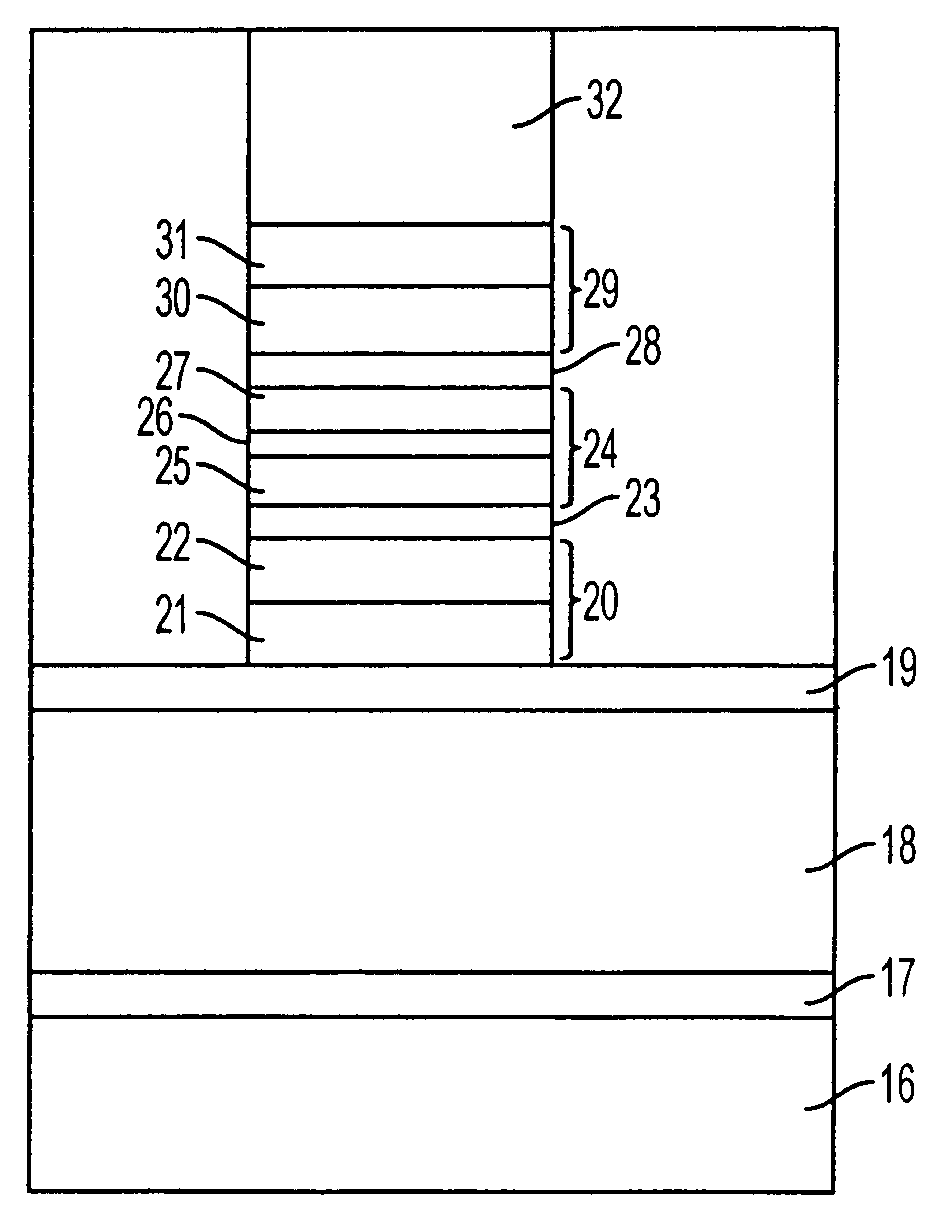
[0013]These and other features and advantages of the invention will be more clearly understood from

Problems solved by technology

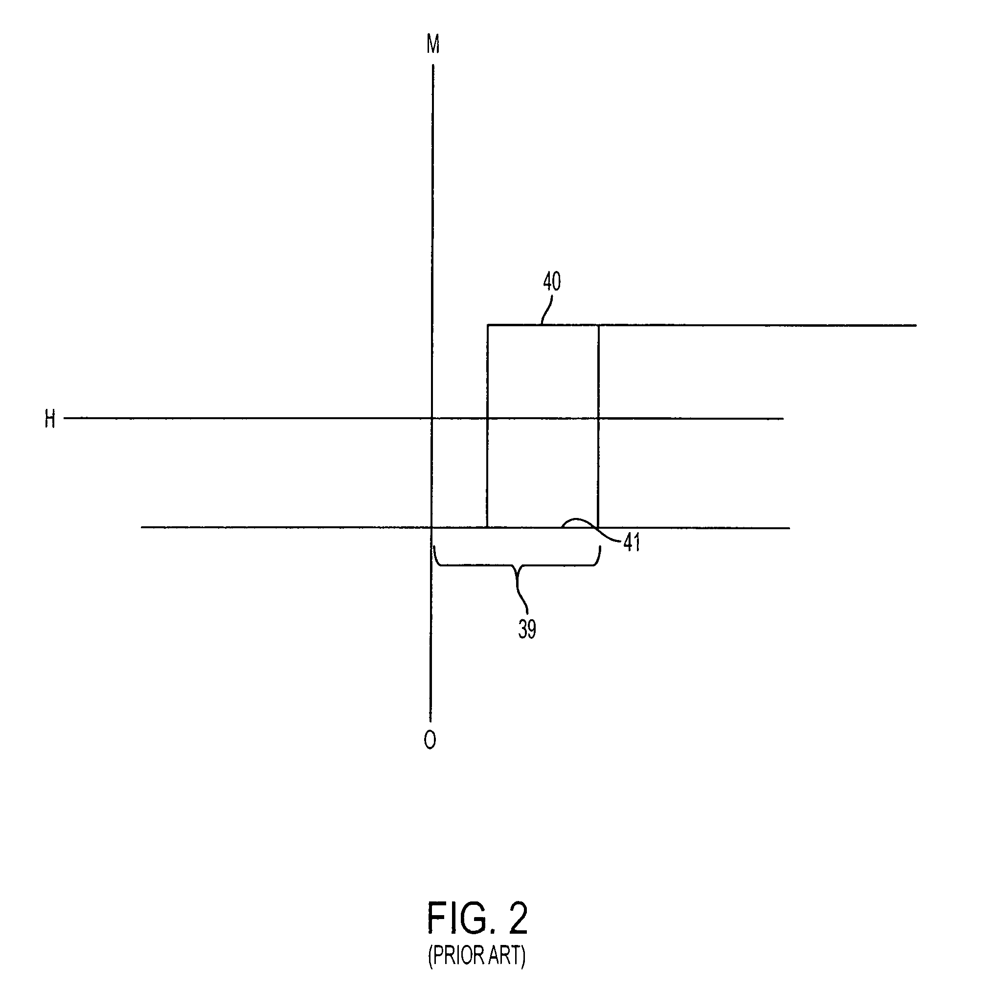
One of the drawbacks of a memory element having a single magnetic tunnel junction as described above is a dramatic decrease in TMR with increased bias voltage.
The decrease or decay in TMR results in a low cell signal and thus, difficulty in reading or sensing the state stored in the cell.
In addition, when a multilayered memory device is scaled down, numerous other problems can occur.
Write current would then need to be driven at the higher current at all times. This makes operation of the MTJ device difficult and leads to excessive power consumption.
As these fields become larger with greater scale down, the problem ex

Method used


Image

  • Magnetic tunnel junction device and its method of fabrication
  • Magnetic tunnel junction device and its method of fabrication
  • Magnetic tunnel junction device and its method of fabrication

Examples


Embodiment Construction

[0022]In the following detailed description, reference is made to various specific embodiments in which the invention may be practiced. These embodiments are described with sufficient detail to enable those skilled in the art to practice the invention, and it is to be understood that other embodiments may be employed, and that structural and electrical changes may be made without departing from the spirit or scope of the present invention.

[0023]The terms “substrate” and “wafer” are used interchangeably in the following description and may include any semiconductor-based structure. The structure should be understood to include silicon, silicon-on insulator (SOI), silicon-on-sapphire (SOS), doped and undoped semiconductors, epitaxial layers of silicon supported by a base semiconductor foundation, and other semiconductor structures. The semiconductor need not be silicon-based. The semiconductor could be silicon-germanium, germanium, or gallium arsenide. When reference is made to the su...


PUM


Abstract

The present invention provides a magnetic tunnel junction memory element comprising two pinned ferromagnetic layers having magnetic orientations pointing in opposite directions and a sense layer arranged between the two pinned ferromagnetic layers and separated from each by a nonmagnetic tunnel barrier layer. The invention also provides methods of fabricating magnetic tunnel junction memory elements as well as magnetoresistive memory devices and processor systems comprising such memory elements.

Description

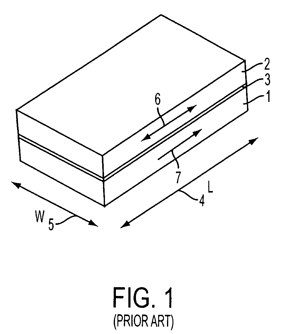
FIELD OF THE INVENTION[0001]This invention relates generally to magnetic tunnel junction (“MTJ”) devices and, more particularly, to those having double tunnel junctions.BACKGROUND OF THE INVENTION[0002]Integrated circuit designers have always sought the ideal semiconductor memory: a device that is randomly accessible, can be written or read very quickly, is non-volatile, and consumes little power. Magnetoresistive random access memory (MRAM) technology has been increasingly viewed as offering all these advantages.[0003]One form of magnetic memory element for an MRAM has a structure that includes ferromagnetic layers separated by a non-magnetic barrier layer that forms a tunnel junction. Information can be stored as a digital “1” or a “0” as directions of magnetization vectors in these ferromagnetic layers. Magnetic vectors in one ferromagnetic layer are magnetically fixed or pinned, while the magnetic vectors of the other ferromagnetic layer are not fixed so that the magnetization d...

Claims


Application Information

Patent Timeline
IPC IPC(8): G11B5/39G11B5/00G11B5/31G11C11/15H01L43/08
CPCB82Y10/00B82Y25/00H01L43/08G11B5/3932G11C11/15G11B5/3909G11B5/313G11B5/3903G11B5/3954G11B2005/0008H10N50/10
Inventor DEAK, JAMES G.
Owner MICRON TECH INC
Why Eureka
Try Eureka