Integrated electric motor and drive, optimized for high-temperature operation

a technology of integrated electric motors and drives, applied in the direction of windings, magnetic circuit rotating parts, magnetic circuit shapes/forms/construction, etc., can solve the problems of reducing the space available within the housing, preventing optimal performance, and resistors and like components adding significantly to the quantity of heat, so as to improve the management of heat transfer and optimize performance.

Inactive Publication Date: 2007-04-03
ORIENTAL MOTOR BOSTON TECH GROUP
View PDF20 Cites 28 Cited by
  • Summary
  • Abstract
  • Description
  • Claims
  • Application Information

AI Technical Summary

Benefits of technology

[0004]It is the broad object of the present invention to provide an integrated motor system wherein and whereby performance is optimized by improved management of heat transfer and dissipation.
[0008]The motor system of the invention will usually include a first housing, substantially enclosing the heat-generating component or components, and an effectively separate second housing substantially enclosing the heat-sensitive component or components, both housings desirably being fabricated from a material (usually, a synthetic resinous material) of relatively low thermal conductivity. The heat-generating component(s) will normally comprise an electronic power-switching device (e.g., a metal oxide semiconductor field effect transistor [MOSFET], an integrated gate bipolar transistor [IGBT], an integrated power module [IPM], or a bipolar transistor), as well as a current-sensing resistor, a power resistor, or both. Generally, all of the heat-generating components utilized in the motor system will desirably be mounted upon a common mounting board, which will advantageously be operatively attached to the motor and fabricated from a metal of high thermal conductivity (e.g., aluminum) so as to more efficiently distribute and dissipate heat and thereby avoid hot spots; other standard PCB substrates, such as for example fiber glass-filled epoxy, can also be employed, but usually with somewhat less thermal advantage.

Problems solved by technology

The thermal sensitivity of certain electronic components employed in contemporary integrated motor systems imposes limits upon the maximum temperature of operation, and thereby precludes optimal performance.
Electronic power switching devices, resistors, and like components add significantly to the quantity of heat that is generated by the motor itself, and the problem is exacerbated in small integrated motor systems where the space available within the housing is very limited (typically in the range of about four to five cubic inches, for NEMA size 23 motors to about 10 cubic inches for NEMA size 34 motors).
These factors are not adequately addressed in conventional integrated motor systems.
All electrical components, including for example heat-generating MOSFETs and heat-sensitive microprocessors (and other integrated circuit devices), are typically contained in a common, closed space defined within the motor drive housing, and the parts and components of the system are not positioned for optimal transfer and dissipation of heat.
It will be appreciated that the space and structural requirements for accommodating and adequately supporting a fan necessarily and substantially increase the size and weight of the overall system, thereby making the arrangement of the Japanese publication particularly unsuitable for use in small, integrated motor systems.

Method used


Image

  • Integrated electric motor and drive, optimized for high-temperature operation
  • Integrated electric motor and drive, optimized for high-temperature operation
  • Integrated electric motor and drive, optimized for high-temperature operation

Examples


Embodiment Construction

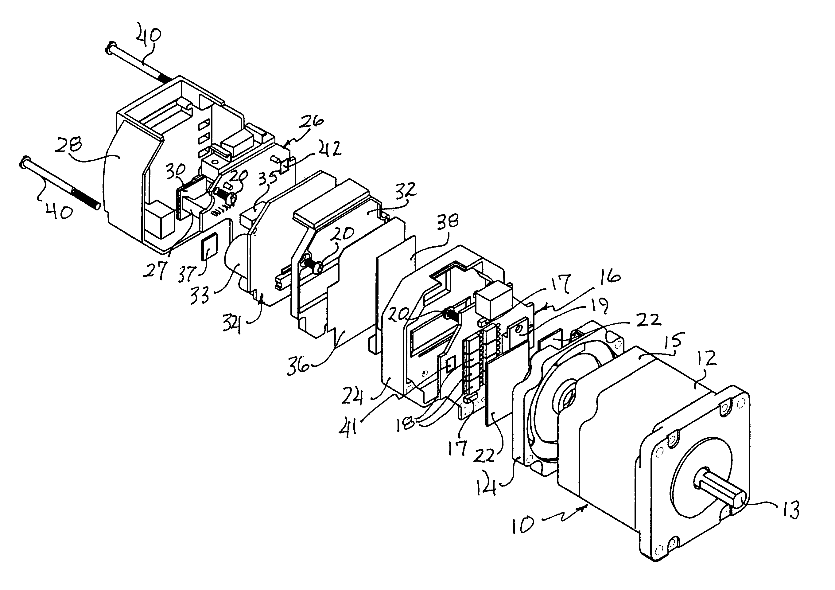
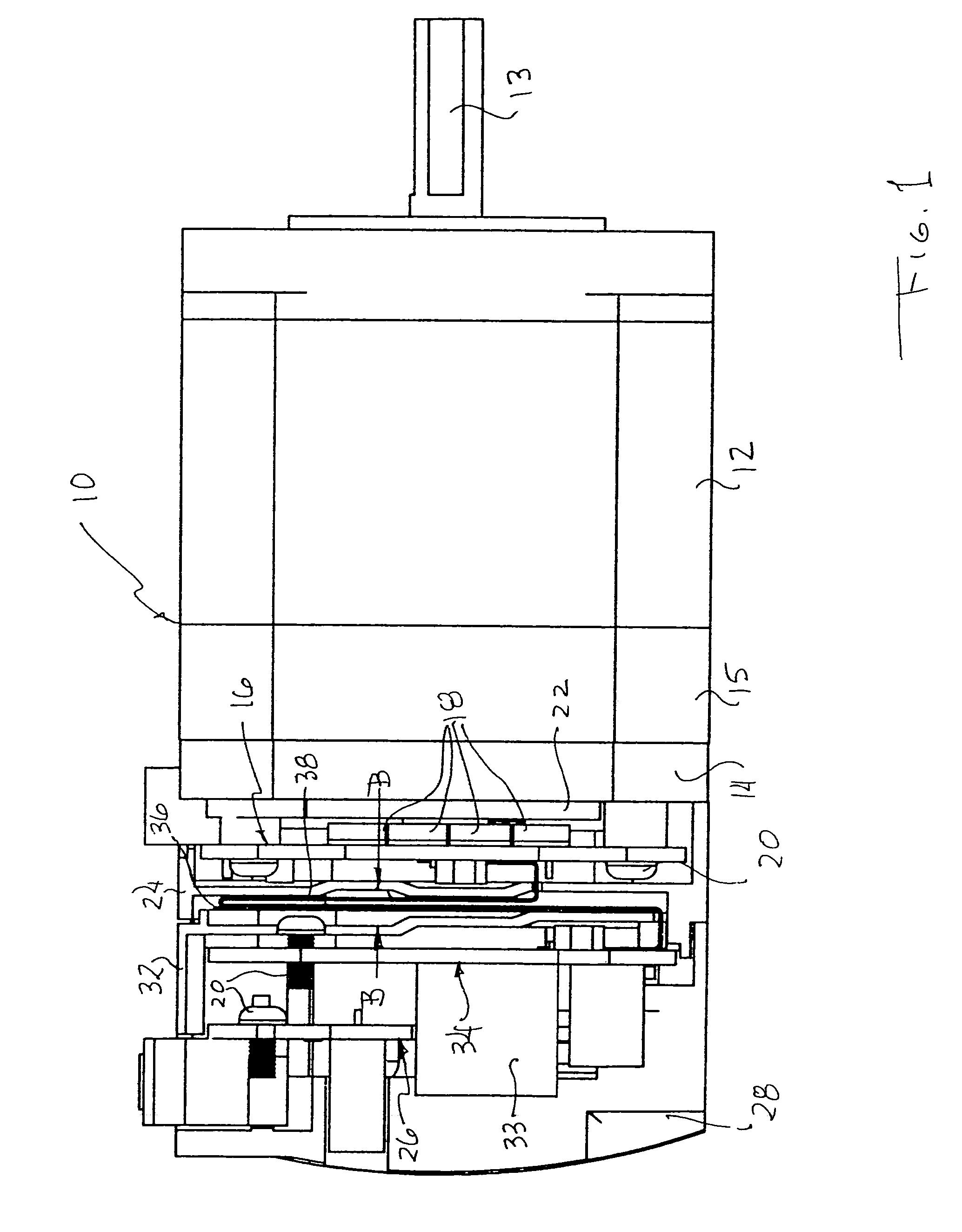
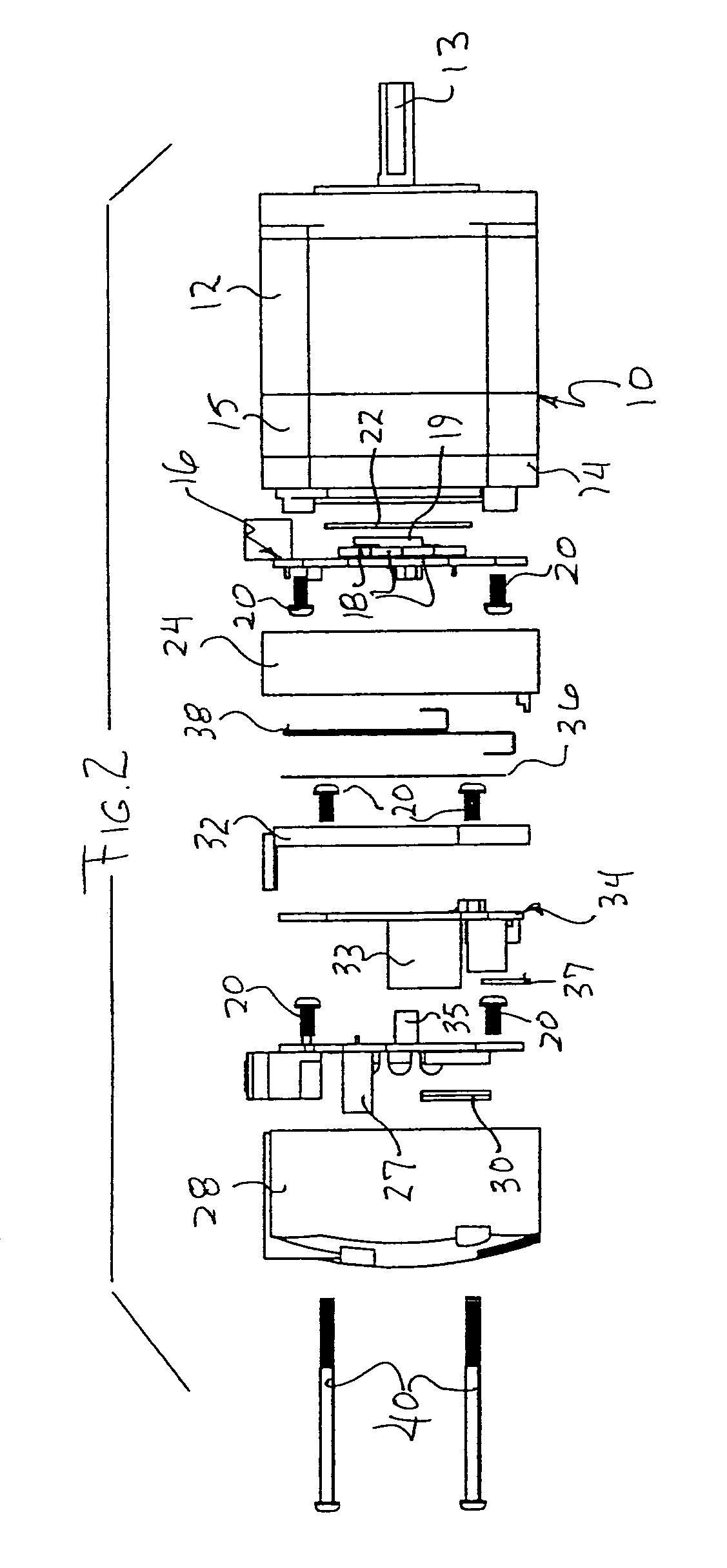
[0014]Turning now in detail to the appended drawings, therein illustrated is an integrated step motor system embodying the present invention and including a motor and sensor assembly, generally designated by the numeral 10, and an adjacent sensor cover 14. The motor includes a body (stator) 12 housing a rotor, the shaft 13 of which is visible, and the assembly includes a sensor housing 15, attached to the motor body. The foregoing components are commonly regarded to together constitute the motor of the system.

[0015]A printed circuit (PC) board, generally designated by the numeral 16, mounts an array of MOSFETs 18 (typically eight) and current-sensing resistors 17 (typically two), as well as a power resistor 19 (which is optional, and may be installed externally to dissipate energy regenerated under heavy braking loads). The board 16 (sometimes referred to herein as the “MOSFET board”) is assembled to the sensor cover 14 by screws 20, and thermal pads 22 are interposed for the effici...


PUM


Abstract

The heat-generating components of an integrated motor system are disposed proximate the motor body, for efficient heat dissipation, and the heat-sensitive components are segregated therefrom, physically and thermally.

Description

BACKGROUND OF THE INVENTION[0001]The thermal sensitivity of certain electronic components employed in contemporary integrated motor systems imposes limits upon the maximum temperature of operation, and thereby precludes optimal performance. Electronic power switching devices, resistors, and like components add significantly to the quantity of heat that is generated by the motor itself, and the problem is exacerbated in small integrated motor systems where the space available within the housing is very limited (typically in the range of about four to five cubic inches, for NEMA size 23 motors to about 10 cubic inches for NEMA size 34 motors).[0002]These factors are not adequately addressed in conventional integrated motor systems. All electrical components, including for example heat-generating MOSFETs and heat-sensitive microprocessors (and other integrated circuit devices), are typically contained in a common, closed space defined within the motor drive housing, and the parts and c...

Claims


Application Information

Patent Timeline
Patent Type & Authority Patents(United States)
IPC IPC(8): H02K11/00H02K1/32H02K3/24H02K9/00H02K5/00
CPCH02K11/0073H02K11/33
Inventor SUZUKI, SEIKISATO, YASUOHODA, AKIHIKOSUGAWARA, CHIKARAARAKI, YOSHINARIOI, EIJIVU, HUNG D.
Owner ORIENTAL MOTOR BOSTON TECH GROUP
Why Eureka
Try Eureka