Coaxial flexible piezoelectric cable polarizer, polarizing method, defect detector, and defect detecting method

a piezoelectric cable and coaxial flexible technology, applied in the direction of generator/motor, variable capacitor, instrument, etc., can solve the problems of unstable fabrication of the cable, inability to detect the presence of the defect, and deterioration of the yield, so as to achieve smooth movement, low friction performance, and maintain the effect of safety

Inactive Publication Date: 2007-04-03
PANASONIC CORP
View PDF12 Cites 4 Cited by
  • Summary
  • Abstract
  • Description
  • Claims
  • Application Information

AI Technical Summary

Benefits of technology

[0032]According to the defect inspecting apparatus of a coaxial flexible piezoelectric cable according to Claim 16, the detecting electrode means is constituted by graphite. Graphite is provided with conductivity and is of low friction performance and therefore, the coaxial flexible piezoelectric member can smoothly be moved.
[0033]According to the defect detecting apparatus of a coaxial flexible piezoelectric cable according to Claim 17, a pole of the direct current voltage applying means connected to the core electrode is maintained at a ground potential. Therefore, even when the human body is brought into contact with the core electrode, safety can be maintained without being electrified.

Problems solved by technology

However, according to the above-described method, when high voltage is applied between the core electrode 1 and the outer electrode 4, a defect of a small crack, a clearance or the like is present in the coaxial flexible piezoelectric member 2.
Further, presence of the defect cannot be detected until high voltage is applied between the core electrode 1 and the outer electrode 4, in other words, until finishing the coaxial flexible piezoelectric cable except polarization and therefore, fabrication thereof becomes unstable and yield is deteriorated.
However, according to the method of the related art, the following problem is posed.

Method used


Image

  • Coaxial flexible piezoelectric cable polarizer, polarizing method, defect detector, and defect detecting method
  • Coaxial flexible piezoelectric cable polarizer, polarizing method, defect detector, and defect detecting method
  • Coaxial flexible piezoelectric cable polarizer, polarizing method, defect detector, and defect detecting method

Examples


embodiment 1

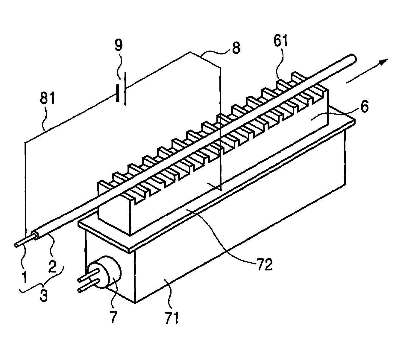
[0062]FIG. 1 is an outlook view showing a constitution of a coaxial flexible piezoelectric polarizing apparatus according to Embodiment 1 of the invention. The coaxial flexible piezoelectric member 2 is formed for the core electrode 1. The molded member is referred to as the piezoelectric tube 3. As the core electrode 1, a coil-like metal line, a line bundled with metal slender lines or the like is used. As the flexible piezoelectric member 2, a composite piezoelectric member of a polymer base material of epoxy resin, urethane resin, chloroprene resin, chlorinated polyethylene resin or the like added with a ceramic piezoelectric powder of titanate zirconate lead or a polymer piezoelectric member of PVDF or the like is used.

[0063]The piezoelectric tube 3 is arranged to the piezoelectric tube path portion 61 provided at the block-like conductor 6 and the piezoelectric tube 3 is moved by moving means (not illustrated). The piezoelectric tube path portion 61 is constituted by a recessed...

embodiment 2

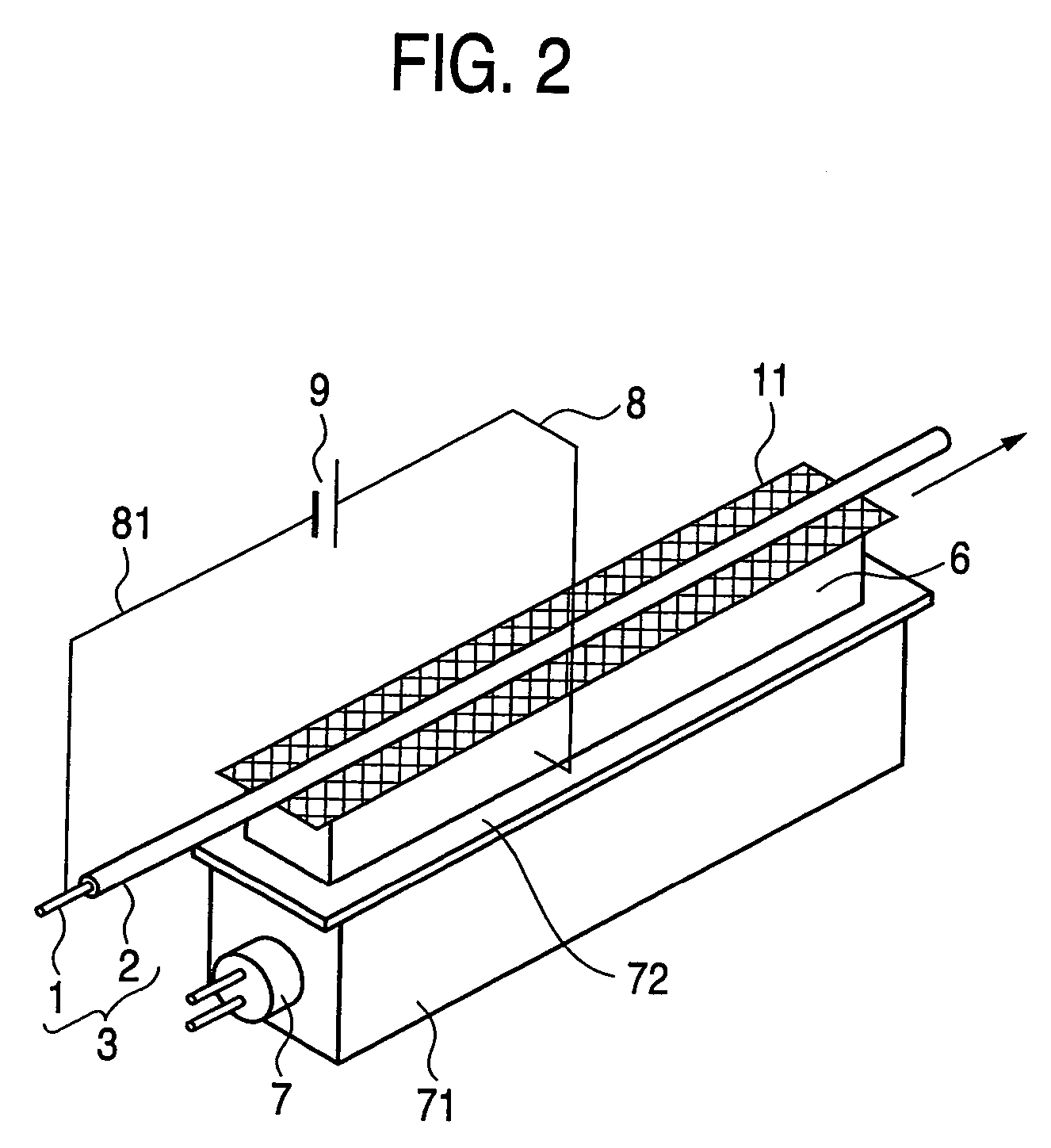
[0067]FIG. 2 is an outlook view showing a constitution of a coaxial flexible piezoelectric polarizing apparatus according to Embodiment 2 of the invention. According to Embodiment 2, the piezoelectric tube path portion is constituted by the metal net 10. The piezoelectric tube 3 is arranged at the metal net 10 provided on a face of the block-like conductor 6 and is moved by moving means (not illustrated). A surface of the metal net 10 is constituted by a recessed and projected shape. By forming recesses and projections by using the metal net 10, the friction force between the piezoelectric tube 3 and the piezoelectric tube path portion (the metal net 10 according to Embodiment 2) without working a surface for arranging the piezoelectric tube 3 in a recessed and projected shape and the piezoelectric tube 3 can be moved by a small force.

[0068]As the metal net 10, a conductor of iron, stainless steel, copper, brass, aluminum or the like is used. According to the embodiment, as the mate...

embodiment 3

[0069]FIG. 3 is an outlook view showing a constitution of a coaxial flexible piezoelectric polarizing apparatus according to Embodiment 4 of the invention. The polarizing apparatus is constituted by providing the groove 11 at the block-like conductor 6, constituting the path portion of the piezoelectric tube 3 by the groove 11 and constituting an inner face of the groove 11 by the recessed and projected shape 62. When the piezoelectric tube 3 arranged at the groove 11 of the block-like conductor 6 is heated by heating the block-like conductor 6, the piezoelectric tube 3 is heated from a bottom face and two wall faces of the groove 11. Therefore, the piezoelectric tube 3 is further uniformly heated and therefore, the coaxial flexible piezoelectric member 2 can be polarized at necessary temperature. Further, an upper portion thereof is opened and the piezoelectric tube 3 can simply be arranged from the upper portion of the groove 11. Further, since the inner face of the groove 11 cons...


PUM

PropertyMeasurementUnit
lengthaaaaaaaaaa
heightaaaaaaaaaa
widthaaaaaaaaaa

Abstract

The invention provides a defect inspecting apparatus and a defect detecting method for specifying a position of a defect before polarization when the defect is included in a coaxial flexible piezoelectric member. Further, when a piezoelectric tube is moved in polarization, a friction force is produced between the coaxial flexible piezoelectric member and a block-like conductor and therefore, a large force is needed in moving the piezoelectric tube. The invention provides a polarizing apparatus and a polarizing method capable of moving the piezoelectric tube even by a small force.
There are provided a defect detecting apparatus of a coaxial flexible piezoelectric member having a constitution of applying a direct current to a coaxial flexible piezoelectric member while moving a piezoelectric tube arranged at a hole of inspecting electrode means and a marking apparatus for marking a defect portion. Thereby, when a defect is present at a portion thereof arranged at the hole of the inspecting electrode means, electricity is discharged at the defect portion and therefore, the defect portion can be specified and the mark can be attached to the defect portion. Further, a conductive block provided with a path portion of the piezoelectric tube is divided. By dividing the block-like conductor by a plural number, a friction force between the block-like conductor per divided one and the piezoelectric tube is reduced. Further, the piezoelectric tube can be moved by a small force by a pulley arranged at a fold back portion of the piezoelectric tube.

Description

TECHNICAL FIELD[0001]The present invention relates to polarization of a coaxial flexible piezoelectric cable. Further, the invention relates to a defect detecting apparatus and a defect detecting method of the cable.BACKGROUND ART[0002]In a background art, as shown by FIG. 7, a coaxial flexible piezoelectric cable of this kind is constituted by forming an outer electrode 4 at an outer surface of a piezoelectric tube 3 formed with a coaxial flexible piezoelectric member 2 at a surrounding of a core electrode 1 and forming a protective core layer 5 at a surrounding thereof.[0003]A flexible piezoelectric cable is generally polarized as follows.[0004]Reference 1 (Piezoelectric composite material comprising piezoelectric ceramic powder and synthetic rubber, Powder and Industry, Vol. 22, No. 1, pages 50–56, 1990) shows that the coaxial flexible piezoelectric member 2 is polarized by applying high voltage between the core electrode 1 and the outer electrode 4. This is disclosed also in U.S...

Claims


Application Information

Patent Timeline
Patent Type & Authority Patents(United States)
IPC IPC(8): H01L41/08G01R29/22H01L41/087H01L41/257H01L41/45
CPCG01R31/083H01L41/087H01L41/45H01L41/257G01R31/021Y10T29/42Y10S310/80G01R31/58H10N30/60H10N30/045H10N30/098H10N30/01
Inventor EBISAWA, MITSUONAGAI, TAKESHISUGIMORI, TOORU
Owner PANASONIC CORP
Why Eureka
Try Eureka