Clock synchronizing method over fault-tolerant Ethernet

a fault-tolerant, clock-synchronizing technology, applied in the field of clock-synchronization, can solve the problems of insufficient accuracy of current methods for power generation requirements, unsuitable techniques for many applications,

Active Publication Date: 2007-04-03
HONEYWELL INT INC
View PDF27 Cites 26 Cited by
  • Summary
  • Abstract
  • Description
  • Claims
  • Application Information

AI Technical Summary

Benefits of technology

[0018]A computing node of the present invention comprises a host computer and a transceiver adapted for connection in a network and a real-time synchronizing circuit. The real-time synchronizing circuit includes a local timer and a logic device that is operable in a master-time transmit mode and in a listen mode. During the master-time transmit mode, the logic device substitutes a current time value of the local timer

Problems solved by technology

Current methods are not accurate enough for power generation requirements of resolution of around 1 millisecon

Method used


Image

  • Clock synchronizing method over fault-tolerant Ethernet
  • Clock synchronizing method over fault-tolerant Ethernet
  • Clock synchronizing method over fault-tolerant Ethernet

Examples


Embodiment Construction

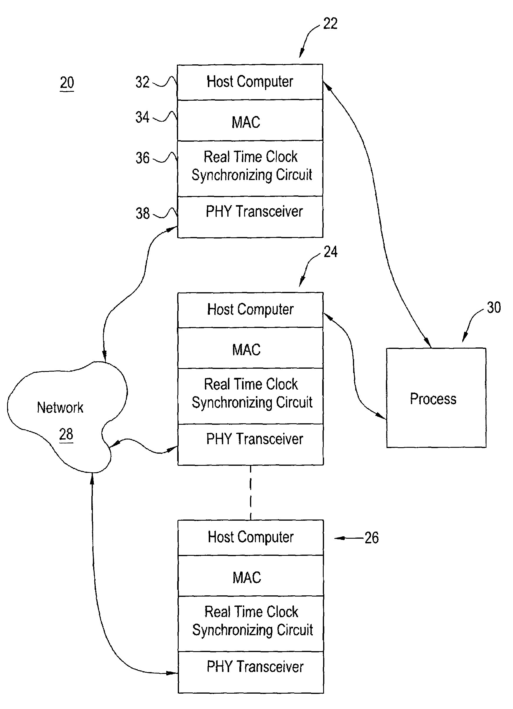
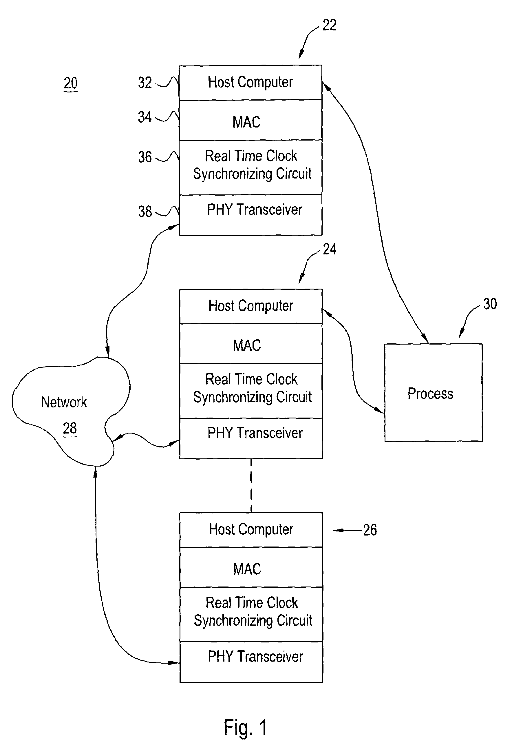
[0030]Referring to FIG. 1, a control system 20 includes a plurality of computing nodes 22, 24 and 26 of the present invention that are disposed to control, monitor and / or manage a process 30. Although three computing nodes are shown, the dashed line between computing nodes 24 and 26 indicates that more or less computing nodes can be used. Computing nodes 22 and 24 are shown with connections to process 30. These connections can be to a BUS to which various sensors and / or control devices are connected. For example, the local BUS for one or more of the computing nodes 22 and 24 could be a Fieldbus Foundation (FF) local area network. Computing node 26 has no direct connection to process 30 and may be used for management of the computing nodes, observation and other purposes.

[0031]Computing nodes 22, 24 and 26 are interconnected via a network 28. Network 28 may be any suitable wired, wireless and / or optical network and may include the internet, an intranet, the public telephone network, ...


PUM


Abstract

A device that recognizes the time synchronization packet and substitutes a real-time value from the master internal counter into the proper place in a data packet is placed between an Ethernet Media Access Controller (MAC) and a Physical Interface Transceiver (PHY). A second device monitors the packet passing from the MAC to the PHY and determines when it is a time synchronization packet from the time master. Upon recognition of the proper packet, the second device simultaneously captures the master's time value and captures the value of a local real-time clock. The result of these captures are presented to the local host computer which controls the time base clock that increments the local real-time clock to either speed up or slow down this local clock, thereby synchronizing the local clock to the time master clock. The offset and skew of the local clock to the master clock is reduced to only the network latency plus variability due to network congestion.

Description

[0001]This Application claims the benefit of U.S. Provisional Application No. 60 / 390,938, filed Jun. 24, 2002.FIELD OF THE INVENTION[0002]The present invention generally relates to clock synchronization among a plurality of computing nodes connected in a network and, more particularly, to methods and devices for accomplishing the synchronization in a fault-tolerant Ethernet environment.BACKGROUND OF THE INVENTION[0003]It is necessary in many applications to synchronize the local clocks of the computing nodes of a network to avoid errors. This is particularly necessary in process control applications wherein the computing nodes are dealing with a sequence of events as clock errors may result in an event being interpreted as wrongly occurring before or after another event. Current methods are not accurate enough for power generation requirements of resolution of around 1 millisecond.[0004]Each computing node in an Ethernet environment generally includes components that are capable of ...

Claims


Application Information

Patent Timeline
IPC IPC(8): H04J3/06H04L7/00H04L12/28
CPCH04J3/0697H04J3/0661H04J3/0664
Inventor GUSTIN, JAY W.
Owner HONEYWELL INT INC
Why Eureka
Try Eureka