Anisotropic nanoparticle amplification of magnetic resonance signals

a technology of anisotropic nanoparticles and magnetic resonance signals, applied in the field of magnetic resonance, can solve the problems of low signal-to-noise ratio in magnetic resonance systems and sensitivity limits

Inactive Publication Date: 2007-04-10
CALIFORNIA INST OF TECH
View PDF7 Cites 69 Cited by
  • Summary
  • Abstract
  • Description
  • Claims
  • Application Information

AI Technical Summary

Problems solved by technology

Sensitivity limits result from the low signal to noise ratio in magnetic resonance systems.

Method used


Image

  • Anisotropic nanoparticle amplification of magnetic resonance signals
  • Anisotropic nanoparticle amplification of magnetic resonance signals
  • Anisotropic nanoparticle amplification of magnetic resonance signals

Examples


Embodiment Construction

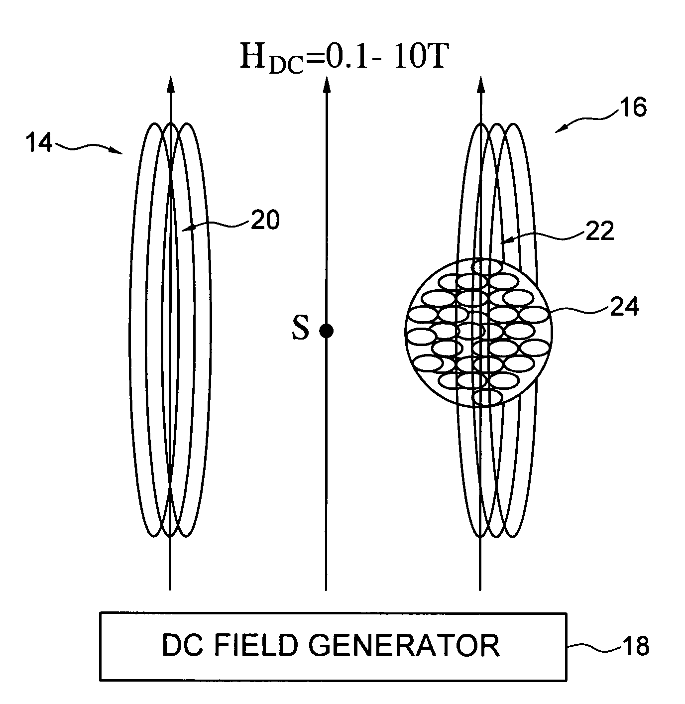
[0032]The invention provides amplification of generated and / or detected alternating transverse magnetic fields produced with inductive coils in the high DC magnetic field conditions typical of magnetic resonance systems. According to the invention, nanoparticles having substantially uniaxial or unidirectional magnetic anisotropy and a reversible transverse susceptibility in the presence of the high DC magnetic field provide either or both of an amplification of the generated signal of an inductive coil or the detected signal of an inductive coil.

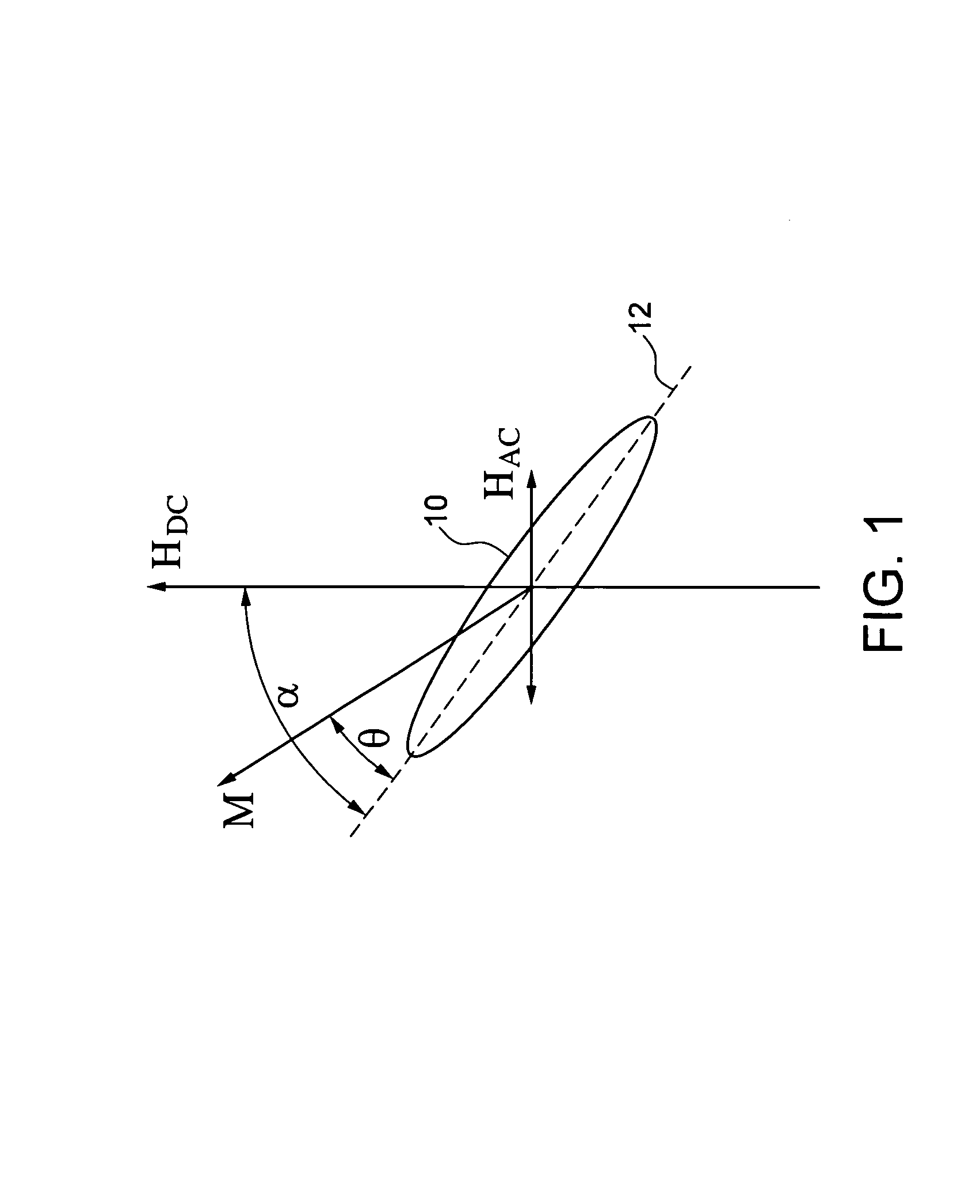
[0033]The invention recognizes that a particular magnetic parameter of nanoparticles has values that may be leveraged in a resonance system to amplify generated and detected signals when the nanoparticles are correctly arranged with respect to an induction coil(s) of a magnetic resonance system. The magnetic parameter of interest is otherwise known as the Reversible Transverse Susceptibility, χRT. The invention demonstrates that properly ori...


PUM


Abstract

The reversible transverse susceptibility of magnetic nanoparticles is used to achieve magnetic flux amplification in magnetic resonance settings. Nanoparticles having substantially uniaxial or unidirectional magnetic anisotropy and a reversible transverse susceptibility in the presence of the high DC magnetic field provide either or both of an amplification of the generated signal of an inductive coil or the detected signal of an inductive coil.

Description

CLAIM FOR PRIORITY AND REFERENCE TO RELATED APPLICATION[0001]This application claims priority under 35 U.S.C. §119 to prior provisional application 60 / 577,907 filed Jun. 7, 2004.FIELD OF THE INVENTION[0002]The invention is the field of magnetic resonance. Example applications of the invention include, but are not limited to, resonance imaging, spectrometry, and atomic resolution microscopy. Additional example applications of the invention include use of the invention in magnetic flux generation devices, and magnetic flux detection devices.BACKGROUND[0003]In devices that rely upon magnetic resonance, a large direct current magnetic field is applied and alternating current is applied for excitation. Sensitivity limits are well-recognized in magnetic resonance devices. Sensitivity limits result from the low signal to noise ratio in magnetic resonance systems. Prior techniques to increase the signal to noise ratio include the use of ever higher magnetic fields, better amplifier technolo...

Claims


Application Information

Patent Timeline
Patent Type & Authority Patents(United States)
IPC IPC(8): G01V3/00G01R33/20
CPCG01R33/20
Inventor BARBIC, MLADEN
Owner CALIFORNIA INST OF TECH
Why Eureka
Try Eureka