[0007]Accordingly, an object of the present invention is to provide an illuminating system which is capable of illuminating an interior of the car cabin with a high level of dramatic effect, without complicating the installment panel of the vehicle.
[0009]With such an arrangement, illumination
modes of the illumination device installed inside a car cabin are operated wirelessly. Therefore, there is no need of installing many switches for controlling the illumination
modes of the illumination device on the installment panel, and hence, the installment panel is simplified in construction. Further, a freedom of not only installment
panel design but also vehicle design is increased. This also leads to reduction of design man-hours. Wiring between the illumination device and the switches is also not needed, and the work of mounting the illumination device is simple and easy. Further, a designer may go ahead with the design work of the illuminating system independently of the design work of the installment panel. Accordingly, a variety of dramatic effects may be incorporated into the illuminating system to thereby present mixed and varied illuminations. And the reduction of the design main-hours is also achieved.
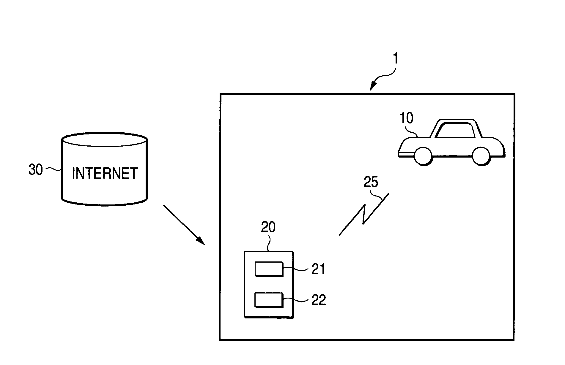
[0011]In the arrangement mentioned above, the illuminating system may arranged such that a plurality of illumination devices are controlled by use of one operation device. The arrangement so made eliminates the necessity of providing the operation device for each illumination device to thereby improve the convenience. A
control unit having a
wireless receiving unit (or a
wireless transceiving unit), which is for controlling illumination modes of the illumination devices, maybe installed in the car cabin. In this case, the wireless receiving unit (or the wireless transceiving unit) receives illumination
mode control data from the operation device, and illumination modes of the illumination devices are controlled in accordance with the received data. In such an arrangement, the data can be collectively received from the operation device. This results in simplification of the whole
system configuration.
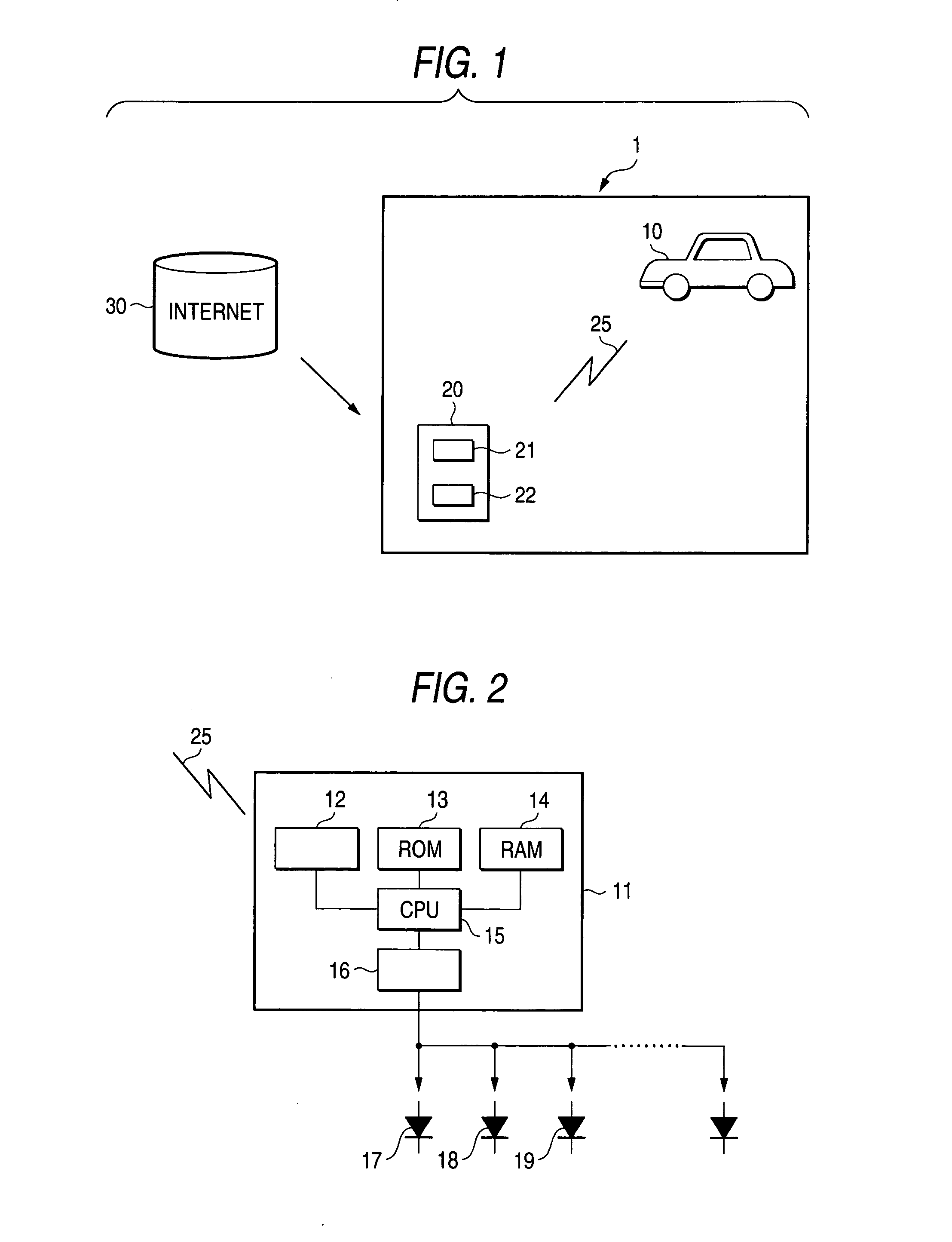
[0012]Examples of the illumination devices are room lamps, lamps for illuminating passenger's feet, door-knob illumination lamps, which are installed for securing a safety when he or she gets in and off the vehicle, a map lamp for assisting the passenger in reading a map, and various lamps installed on the ceiling or the like for the purpose of decorating the interior of the car cabin. The types of light sources used for those illumination devices are not limited in particular. For example, LEDs, bulbs, fluorescent lamps, and cold-
cathode tubes maybe used for the light sources. Above all, use of the LEDs is preferable. The LED is small in size, and needs a less space for the
light source installation. Accordingly, use of LEDs contributes to
size reduction and
thinning of the illumination device. The use of the LEDs fulfills the demand of energy saving since the
power consumption of them is small. Further, the LED has a small heating value, so that it less affects its members around it. Accordingly, the illumination device may be designed to be compact, and a freedom of mounting the illumination device is increased. Further, the LED is long in service life. This feature is advantageous in the light of maintenance. Furthermore, the LED is resistant to vibration and
impact. This feature provides a reliable illumination device. Additionally, a response speed of the LED is high. Therefore, the turning on and off of the LED, luminance adjustment, a change of emitting light color (when a LED capable of emitting lights of at least two colors is used) are easily and instantaneously performed. By utilizing such LED characteristics, various illumination modes may be created. A type of the LED is not limited, and any of various types of LEDs, such as a shell-type of LED and a
chip-type of LED, may be used.
[0014]Communication means used for the wireless communication between the operation device and the illumination device is not limited to specific ones. For example,
Bluetooth™ (
Bluetooth SIG Inc.) may be used for the communication means. Use of such a simple wireless function is advantageous in that it is low in price. Where the
Bluetooth™ is used, a
short distance communication is possible at a high level of security. Where the Bluetooth™ is used, a high level of compatibility with other devices is secured. Accordingly, the operation device of the invention may be used as an operation device of other devices (inclusive of the devices installed on the vehicle and used outside the vehicle).
[0015]A portable
information processing terminal or a portable communication terminal may be used for the operation device. Specific examples of them are a PDA, a
laptop personal computer, a portable telephone set, and PHS. Utilization of such an existing device improves user's convenience. In particular, those users who own the portable communication terminals do not need to buy new interface devices. A dedicated operation device may be used, as a matter of course. In this case, the following advantages are present: functions may be incorporated into the operation device as desired, and a design freedom of designing the
user interface is increased.

