Narrow band electric discharge gas laser having improved beam direction stability

a gas laser and beam direction technology, applied in the direction of instruments, photomechanical equipment, active medium materials, etc., can solve the problems of affecting the laser gain and energy stability, affecting the alignment of front and rear laser optics, and affecting the stability of the beam direction, so as to reduce the fluctuation of the laser beam direction, improve the wavelength stability, and improve the effect of wavelength stability

Inactive Publication Date: 2007-04-10
CYMER INC
View PDF7 Cites 2 Cited by
  • Summary
  • Abstract
  • Description
  • Claims
  • Application Information

AI Technical Summary

Benefits of technology

[0012]The present invention provides an electric discharge, narrow band gas laser with improvements in wavelength stability. Improvements result from reduced laser beam directional fluctuations or fast correction of those fluctuations. Applicant has discovered, using an extremely sensitive knife edge optical technique, that gas discharge laser windows in a trapezoidal configuration were causing slight wavelength perturbations when laser gas density varied during laser operation. The optical technique involves using test laser beam directed through the discharge region of the gas discharge laser, blocking a portion of the beam with a knife edge and measuring the non-blocked portion of the beam to monitor beam deflection. With this technique, Applicant can measure beams deflection with an accuracy of about 0.3 microradians and with a time response of about 1 microsecond. An im...

Problems solved by technology

If the mirrors are normal to the laser beam axis the beam will suffer about 4% reflection loss at each window-gas interface and reflection from windows in the normal position may be detrimental to the laser gain and energy stability.
This complicates the alignment of the front and rear laser optics especially for larg...

Method used


Image

  • Narrow band electric discharge gas laser having improved beam direction stability
  • Narrow band electric discharge gas laser having improved beam direction stability
  • Narrow band electric discharge gas laser having improved beam direction stability

Examples


Embodiment Construction

Knife Edge Experiments

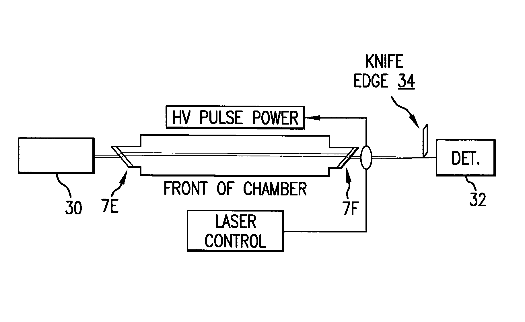
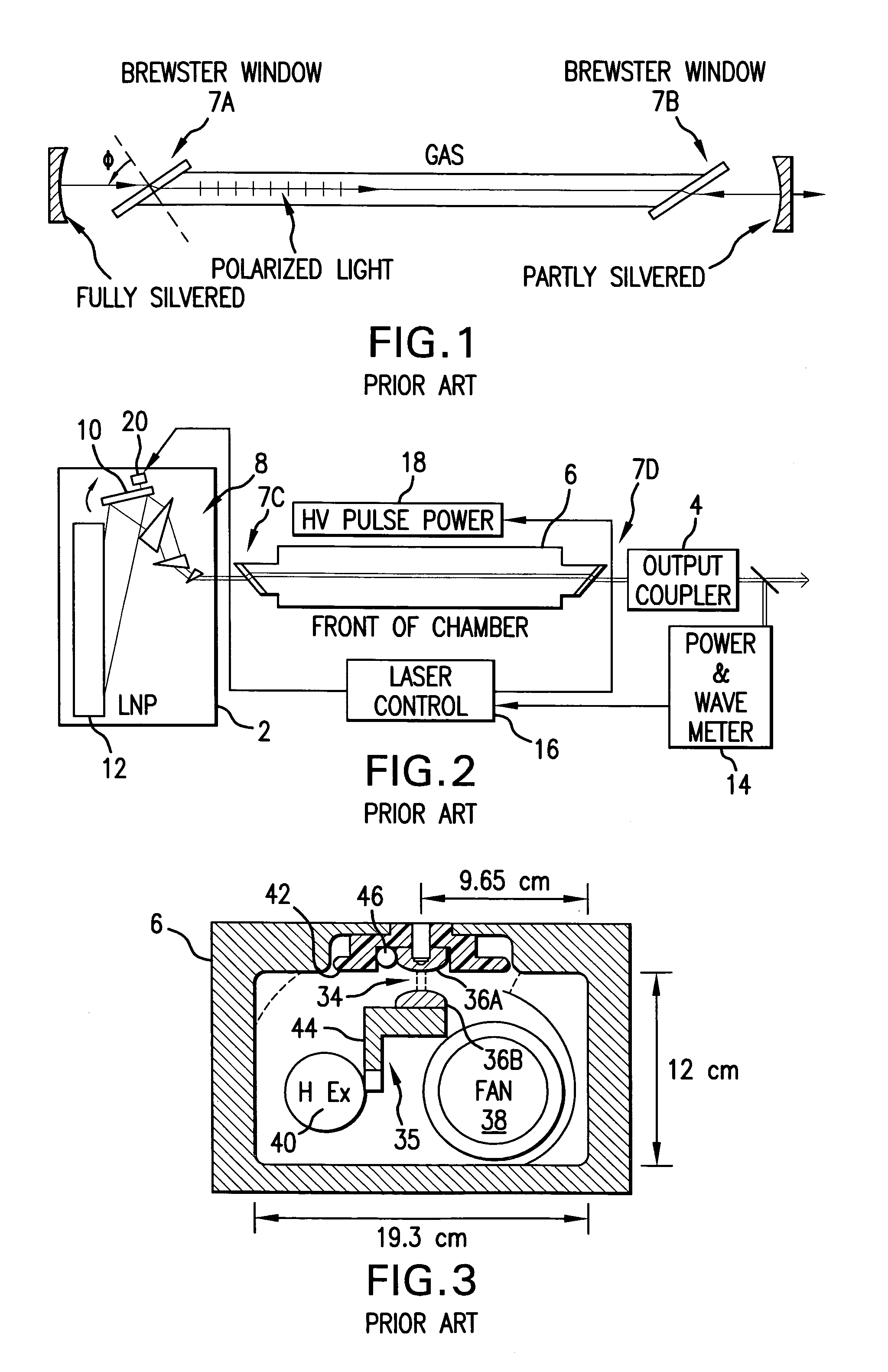
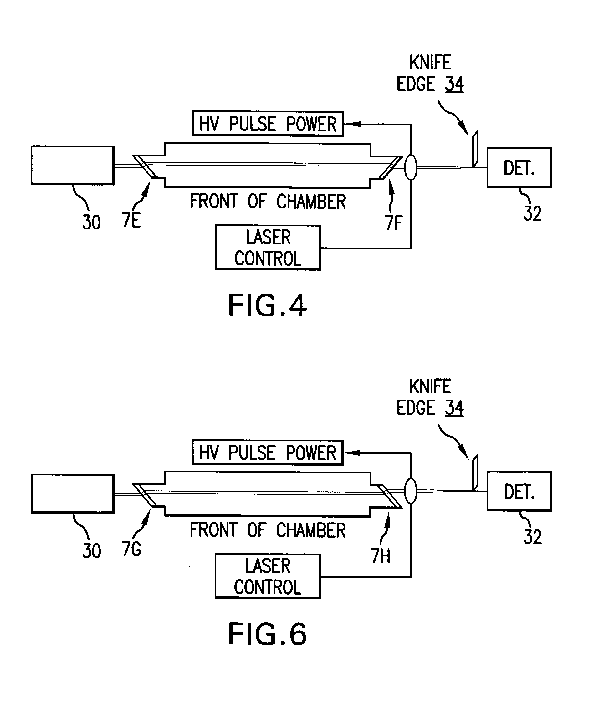
[0026]Applicant has conducted extensive experiments to determine the causes and effects of beam bending within the laser gas of the type of electric discharge lasers described in FIG. 2. A slightly simplified version of his basic experimental set up is shown in FIG. 4. The output coupler and the LNP were removed and replaced with a transilluminating diode laser (Model No. 31-0334 by Coherent, Inc. with offices in Santa Clara, Calif.) 30, lens 31, a diode detector (Model No. DET 200 by ThorLabs, Inc. with offices in Newton, N.J.) 32 and a knife edge 34 which cut about 50 percent off from one side of the laser beam all as shown in FIG. 3. Diode laser 30 is a small inexpensive laser producing a continuous visible light, red beam at a wavelength of 635 nm. Any bending of the beam shows up as a change in the intensity of the light from laser 30 measured by detector 32. During a set of tests, the laser was discharged and the fan was operated at a normal speed of abou...


PUM


Abstract

An electric discharge, narrow band gas laser with improvements in wavelength stability. Improvements result from reduced laser beam directional fluctuations or fast correction of those fluctuations. Applicant has discovered, using an extremely sensitive knife edge optical technique, that gas discharge laser windows in a trapezoidal configuration were causing slight wavelength perturbations when laser gas density varied during laser operation. The optical technique involves using test laser beam directed through the discharge region of the gas discharge laser, blocking a portion of the beam with a knife edge and measuring the non-blocked portion of the beam to monitor beam deflection. With this technique, Applicant can measure beams deflection with an accuracy of about 0.3 microradians and with a time response of about 1 microsecond. An improvement in wavelength stability is achieved by orienting the laser chamber windows parallel to each other at a selected angle between 40° and 70° with the laser beam direction. The change eliminates wavelength fluctuations caused by laser beam direction fluctuation caused pressure fluctuations and the prism effect resulting from windows mounted in a prior art trapezoidal configuration. Beam directional fluctuations can also be measured during laser operation using the knife edge technique or similar fast response techniques such as a quadrant detector and the measured values can be used in a feedback arrangement along with fast wavelength control unit to compensate for changes in beam direction. In addition techniques for reducing the causes of beam direction fluctuations are disclosed. These include techniques for minimizing the effects of laser discharge caused pressure waves.

Description

[0001]This invention is a continuation-in-part of Ser. No. 09 / 490,835 filed Jan. 25, 2000. This invention relates to gas discharge lasers and especially to narrow band, high pulse rate electric discharge gas lasers with rapidly circulating laser gas and to methods of testing and of stabilizing laser beam direction in such lasers.BACKGROUND OF THE INVENTION[0002]Gas lasers typically contain a laser gas contained in a laser chamber. Normally two windows are provided for a laser beam to pass into and out of the chamber. These windows may be positioned normal to the laser axis or they may be positioned at various angles with respect to the beam axis. If the mirrors are normal to the laser beam axis the beam will suffer about 4% reflection loss at each window-gas interface and reflection from windows in the normal position may be detrimental to the laser gain and energy stability. By tilting the windows, even slightly, reflection caused problems can be reduced. By tilting the windows to ...

Claims


Application Information

Patent Timeline
IPC IPC(8): H01S3/22H01S3/10G03F7/20H01S3/036H01S3/038
CPCG03F7/70025G03F7/70575G03F7/708H01S3/036H01S3/038H01S3/0381H01S3/0382
Inventor BOR, ZSOLT
Owner CYMER INC
Why Eureka
Try Eureka