Light source unit and display device having luminance control based upon detected light values

Inactive Publication Date: 2007-04-24
MITSUBISHI ELECTRIC CORP
View PDF12 Cites 72 Cited by
  • Summary
  • Abstract
  • Description
  • Claims
  • Application Information

AI Technical Summary

Benefits of technology

[0018]In the second light source unit, the light source controller may control luminance of each of the plurality of the light source elements based on a change in a value detected by the temperature detector so as to suppress a change in chromaticity of the light source unit. This configuration allows effectively controlling the light source in accordance with spectrum changes caused by changes in the temperature of the light source.
[0019]In the first or second light source unit, the light source may comprise a plurality of light source elements emitting light with wavelengths corresponding to each of N (N is a natural number) number of colors, and the light detector may comprise N number of optical sensors corresponding to each of N number of colors. The light source controller may control each of the plurality of light source elements so that each value detected by the N number of optical sensors approaches each given value. This configuration allows more accurate control of the light source.
[0020]In the second light source unit, the light source controller may control each of the plurality of light source elements to emit light with luminance corresponding to a temperature value detected by the temperature detector. This configuration allows effectively controlling the light source in accordance with spectrum changes caused by changes in the temperature of the light source.
[0021]The first display device according to the present invention has a light source unit and a display panel for displaying images by controlling light emitted by the light source unit. The light source unit has a light source comprising a plurality of light source elements for

Problems solved by technology

Though LEDs have good color characteristics, they have somewhat instable emission characteristics.
Such a sensor, however, is hard to manufacture and hence it is difficult to obtain an optical sensor with desired properties.
Though sensors with the bandpass filter can detect a change in a luminance level within a wavelength band, it cannot accurately detect a change in spectrum (change in col

Method used


Image

  • Light source unit and display device having luminance control based upon detected light values
  • Light source unit and display device having luminance control based upon detected light values
  • Light source unit and display device having luminance control based upon detected light values

Examples


first embodiment

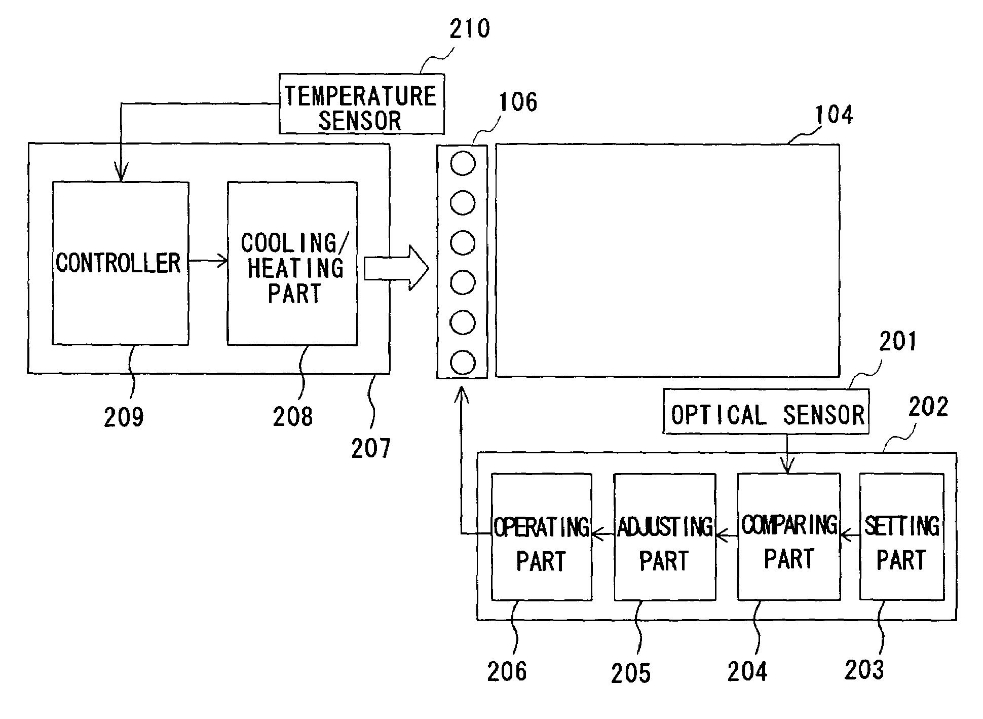
[0030]The first embodiment controls the temperature of a light source comprising a plurality of light source elements emitting different wavelengths of light. This embodiment keeps the light source unit at constant temperature or temperatures and thereby effectively controls the luminance and chromaticity of the light emitted by the light source elements.

[0031]FIG. 1 is a sectional view to explain an overall structure of a liquid crystal module according to this embodiment. It shows a schematic structure of a liquid crystal display module 100 having a sidelight type backlight unit. The liquid crystal display module 100 includes a backlight unit 101 and a liquid crystal display panel 102 with driver circuits (not shown). The backlight unit 101 has an optical sheet 103 such as a prism sheet for collecting light to increase the front luminance, a diffusion sheet for diffusing transmitted light to achieve the uniform surface luminance, and the like. The backlight unit 101 also has a lig...

second embodiment

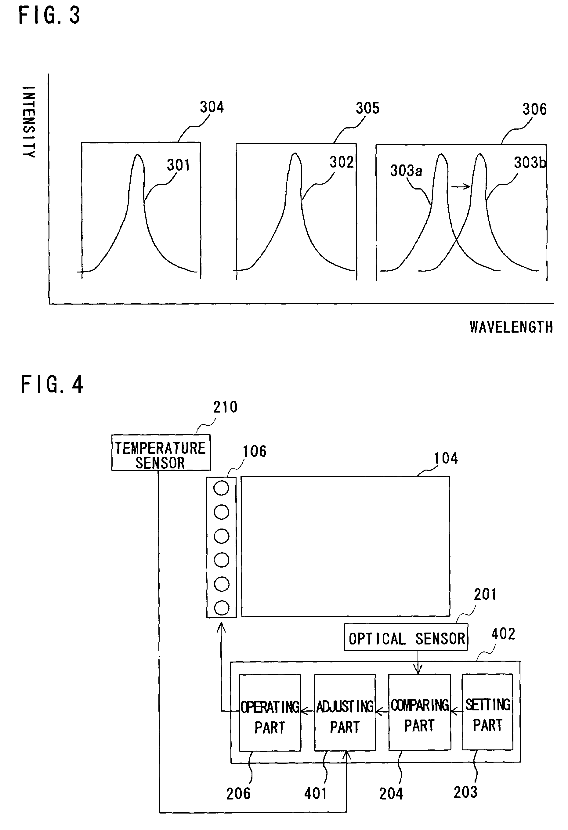
[0048]FIG. 4 is a view to explain a schematic structure of a light source unit according to the second embodiment of the present invention. In FIG. 4, the same reference symbols as in FIG. 2 designate the same elements and redundant description will be omitted. The light source unit according to this embodiment does not have the temperature control section 207 shown in FIG. 2. The light source unit in FIG. 4 has a light source control section 402 including an adjusting part 401. The adjusting part 401 determines the feedback amount for controlling the light source 106 based on the value detected by the temperature sensor 210. The adjusting part 401 pre-stores different feedback coefficients or calculates different feedback coefficients corresponding to temperature values. Each of the feedback coefficients is associated with each of different temperature values or temperature ranges. The light source unit is controlled by the feedback control based on the temperature of the light sou...

third embodiment

[0053]FIG. 5 is a view to explain a schematic structure of a light source unit according to the third embodiment of the present invention. In FIG. 5, the same reference symbols as in FIG. 2 designate the same elements and redundant description will be omitted. The light source unit in FIG. 5 has a temperature control section 501 for controlling the light source 106 according to different temperature. The temperature control section 501 includes the cooling / heating part 208 and a controller 502. The cooling / heating part 208 has the same structure as the one in the first embodiment. The controller 502 can change the set temperature of the light source 106. For example, it controls the cooling / heating part 208 so that the temperature of the light source 106 approaches a selected one of a plurality of different specific temperature values or temperature ranges.

[0054]For example, when the outside temperature rises and the light source 106 is unable to maintain the first temperature, the ...


PUM


Abstract

A light source unit includes a light source having LED chips for emitting different colors of light and an optical sensor for detecting light from a light mixer. A light source control section controls by feedback control luminance of each of the LED chips according to values detected by the optical sensor. The light source unit also includes a temperature control section for controlling the temperature of the light source. The temperature control section is a feedback control system. Keeping the light source at a constant temperature allows suppressing spectrum changes of the LED chips with temperature, thereby suppressing changes in the luminance and chromaticity of the light source unit.

Description

BACKGROUND OF THE INVENTION[0001]1. Field of the Invention[0002]The present invention relates to a light source unit and a display device, and more specifically, to a light source unit and a display device capable of effective control of a light source comprising a plurality of light source elements with different emission frequencies.[0003]2. Description of the Related Art[0004]Liquid crystal display devices have become widely used as image display devices for personal computers and various types of monitors. Liquid crystal display devices generally include a liquid crystal display panel and a backlight unit mounted on the back of the panel. Liquid crystal display panels display images by controlling transmission of light. Backlight units generally include a light source and a plurality of optical components for effectively emitting the light from the light source toward the liquid crystal display panel. Cold cathode fluorescent lamps (CCFLs) and light emission diodes (LEDs) are we...

Claims


Application Information

Patent Timeline
IPC IPC(8): G01G1/32G09G3/30G09G5/00G09G5/10H05B37/02G02F1/13357G02F1/133G09G3/20G09G3/34G09G3/36H05B44/00
CPCH05B33/0872H05B33/0869G02F2001/133628H05B45/22H05B45/28G02F1/133628G02F1/1335
Inventor ISHIGUCHI, KAZUHIRO
Owner MITSUBISHI ELECTRIC CORP
Why Eureka
Try Eureka