
Tubular support for shock tower in automobiles

a technology for automobiles and shock towers, which is applied in the direction of roofs, transportation and packaging, vehicle arrangements, etc., can solve the problems of incompatibility of mig welding and high production assembly plants, and achieve the reduction of the number of welds and the number of weld stations needed in the manufacturing process at the assembly plant, and the effect of lowering manufacture and assembly costs

Inactive Publication Date: 2007-05-01
FORD GLOBAL TECH LLC
View PDF25 Cites 29 Cited by
  • Summary
  • Abstract
  • Description
  • Claims
  • Application Information

AI Technical Summary

Benefits of technology

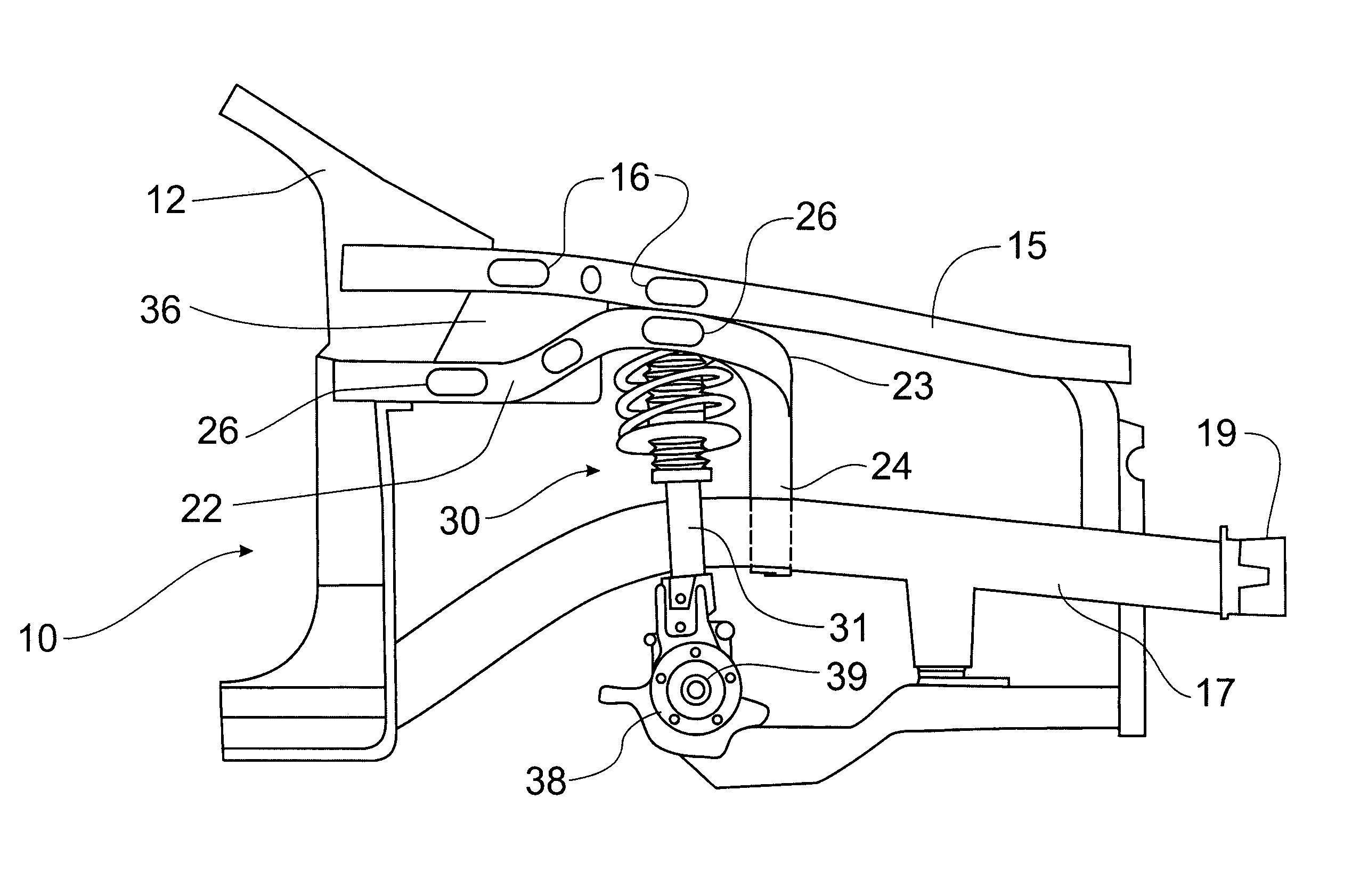
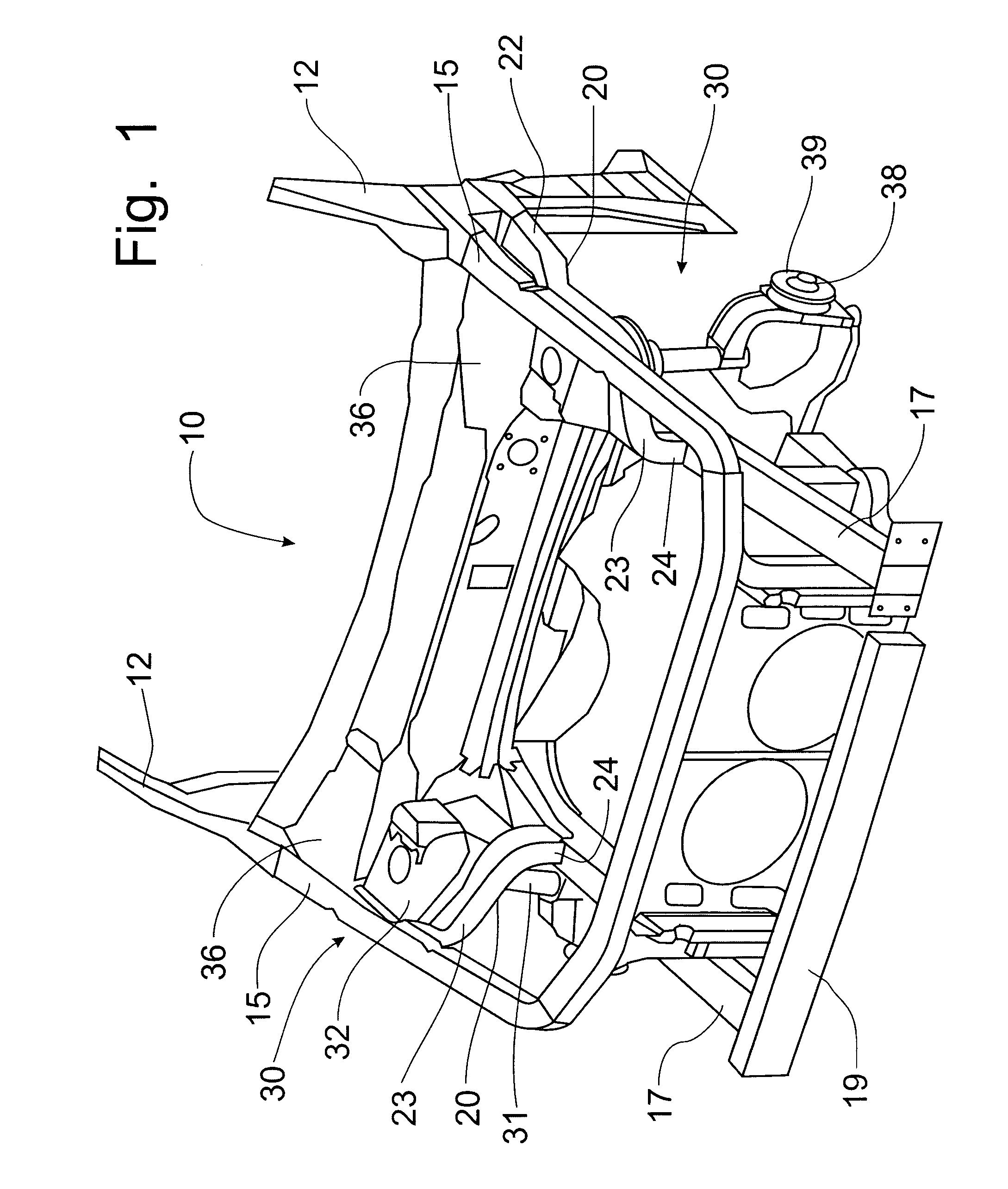
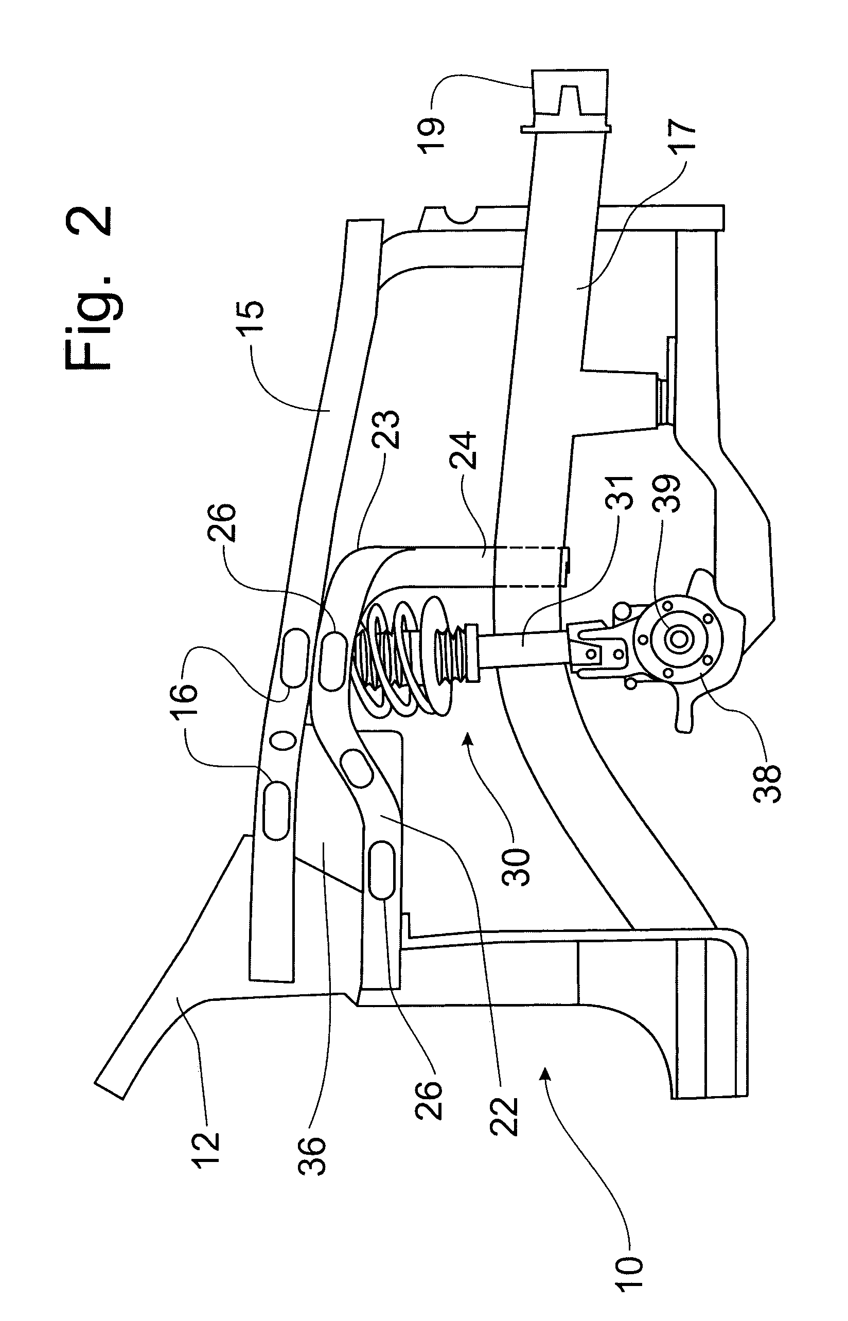
This patent describes a new shock tower support structure for automotive vehicles that improves crash force resistance and reduces manufacturing and assembly costs. The support structure utilizes a hydroformed tubular member that wraps around the front edge and upper portion of the shock tower assembly to join into the lower vehicle frame rail. The support is spot-welded to the upper vehicle frame and arc-welded to the lower vehicle frame, providing improved stiffness in the support of the vehicle shock tower assembly. The support structure also provides increased crash resistance for front impacts into the vehicle. The steel front apron in conventional shock tower supports can be replaced by a plastic panel that has associated components pre-assembled thereon to be installed as a module. Overall, this patent describes a durable, inexpensive, facile, and simple-effective shock tower support structure for automotive vehicles.

Problems solved by technology

MIG welding, on the other hand, is not compatible with a high production assembly plant.

Method used


Image

  • Tubular support for shock tower in automobiles
  • Tubular support for shock tower in automobiles
  • Tubular support for shock tower in automobiles

Examples


Embodiment Construction

[0027]Referring to FIGS. 1–4, a tubular front structure, including a shock tower support, forming a part of the front end of an automobile frame and incorporating the principles of the instant invention can best be seen. The frame 10 of the automobile is preferably formed from hydroformed tubular members. Such tubular members can be spot-welded to form an integral frame assembly for the front end of a vehicle.

[0028]Hydroforming is a process by which a standard tubular stock member is placed into a form shaped to correspond to the particular member to be formed and to correspond to the particular section required for the frame design. A liquid is then introduced into the interior of the tubular stock and pressurized until the tubular stock expands to assume the shape defined by the configured form. The expanded and re-shaped tubular stock now has a substantially different shape. By forming cutouts and other access openings into the re-shaped tubular member, spot-welding electrodes ca...


PUM


Abstract

A shock tower support structure utilizes a hydroformed tubular member that extends horizontally along the upper vehicle frame rail and wraps around the front edge and upper portion of the shock tower assembly to join into the lower vehicle frame rail. The shock tower support member is welded to the upper vehicle frame and also to the lower vehicle frame. The loading of the spot welds is in shear to provide improved stiffness in the support of the vehicle shock tower assembly. The support structure also provides increased crash resistance for front impacts into the vehicle. The front apron in conventional shock tower supports can be replaced by a plastic panel that has associated components pre-assembled thereon to be installed into the vehicle as a module.

Description

CROSS-REFERENCE TO RELATED APPLICATIONS[0001]This application claims domestic priority on U.S. Provisional Patent Application Ser. No. 60 / 564,432, filed Apr. 22, 2004, the contents of which are incorporated herein by reference.BACKGROUND OF THE INVENTION[0002]Manufacturing processes for automobile frames are evolving from one that currently utilizes MIG welding processes, i.e. an arc welding process in which a line of molten material is deposited by the welder in joining two pieces of metal together, to a spot-welding process. Spot-welding, a process involving the passage of electrical current between two electrodes to melt and join two pieces of metal placed between the electrodes, is being utilized in a greater degree in the manufacturing of automotive vehicles. Spot-welding requires a frame design that is conducive to being assembled using the spot-welding process. For example, if two tubular members are being spot-welded, access to the adjoining walls of the two tubular members ...

Claims


Application Information

Patent Timeline
Patent Type & Authority Patents(United States)
IPC IPC(8): B62D21/11B62D25/08
CPCB62D21/11B62D25/088
Inventor MOUCH, TIMAZZOUZ, MICHAELAZZOUZ, MUSA
Owner FORD GLOBAL TECH LLC
Learn More