Three-dimensional imaging system for pattern recognition

a three-dimensional imaging and pattern recognition technology, applied in the field of imaging systems, can solve the problems of high-throughput application or surveillance systems, difficult to capture the center of a finger, and degrade the accuracy of optical scanning, and achieve the effects of fine resolution, large focal length variation, and fast response tim

Active Publication Date: 2007-05-01
STEREO DISPLAY
View PDF6 Cites 62 Cited by
  • Summary
  • Abstract
  • Description
  • Claims
  • Application Information

AI Technical Summary

Benefits of technology

[0013]The present invention provides a real-time three-dimensional imaging system for pattern recognition having a wide depth of field, a high depth resolution, a fast acquisition time, a variable field of view for magnification, a variable optical axis for tracking, and capability of compensating various optical distortions and aberrations, which enables pattern recognition system to be more accurate as well as more robust to environmental variation.

Problems solved by technology

The accuracy of optical scanning can be degraded by latent images left from previous users and wear of coating and CCD.
The silicon technology provides a high resolution image using the DC capacitance between a silicon sensor and the finger, but careful scanning process and verification is required due to its inherent small sensor size, which makes capturing the center of a finger difficult.
While these biometric applications provide great accuracy, these systems require user's cooperation because the finger or the iris need to be carefully positioned relative to the sensor, which can cause problems in a high-throughput application or surveillance system.
Majority of face recognition algorithms uses two-dimensional images and their accuracy is greatly subject to environmental factors including face pose, illumination, cosmetics, and face expression.
While three-dimensional face recognition approaches promise to resolve their two-dimensional counterpart problems, a major challenge on three-dimensional face recognition systems is the acquisition of three-dimensional images for both facial database and surveillance.
Bowyer et al. described the problems related to these conventional sensors, which include a narrow depth of field, lower depth resolution, and longer acquisition time.
The aforementioned problems can be more critical to the non-intrusive approach, where a subject is unaware of surveillance or moving.
In this case, the subject can not be positioned at the optimal working range of an imaging system, while most three-dimensional imaging systems have a limited range of depth of field.
In this speed, it is almost impossible to obtain usable images of the subject who is moving.

Method used


Image

  • Three-dimensional imaging system for pattern recognition
  • Three-dimensional imaging system for pattern recognition
  • Three-dimensional imaging system for pattern recognition

Examples


Embodiment Construction

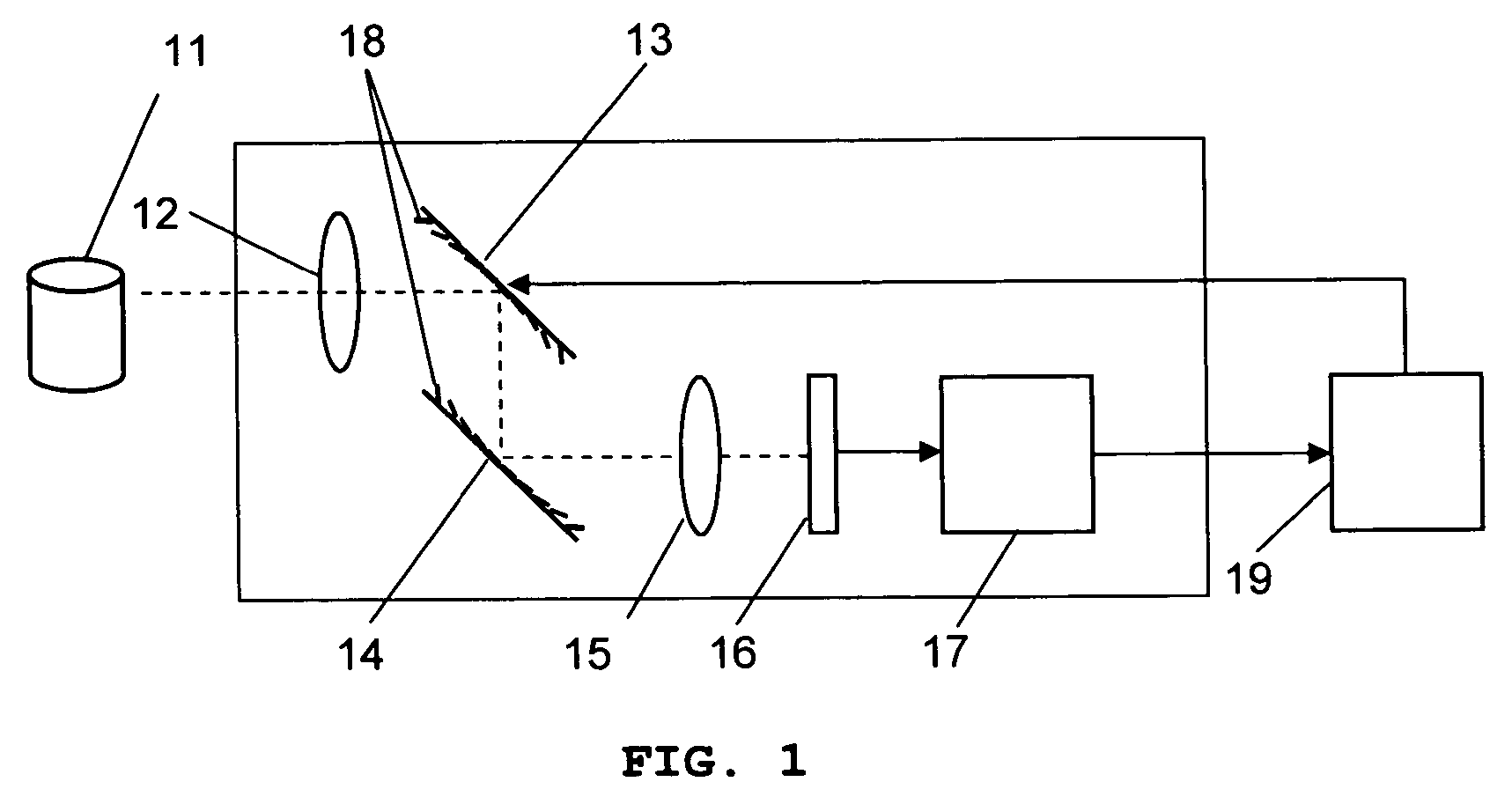
[0036]FIG. 1 illustrates a real-time three-dimensional imaging system for pattern recognition according to the preferred embodiment of the present invention. The imaging system takes an image from the object 11 by using an objective lens 12, the first variable focal length lens 13, the second variable focal length lens 14, and an auxiliary lens 15. The imaged pattern in an image sensor 16 is processed by an image processing unit 17. The image sensor 16 receives two-dimensional images with different focal planes that are shifted by changing the focal length of the variable focal length lens 14. The image processing unit 17 extracts in-focus pixels or areas from original pictures with different focal planes to generate an all-in-focus image with depth information. The focal length of the variable focal length lens 14 is changed without the macroscopic movement of the lens system or time delay since each micromirror 18 of the variable focal length lenses 14 is actuated by electrostatic...


PUM


Abstract

The present invention provides a real-time three-dimensional pattern recognition imaging system having a variable focal length, a wide depth of field, a high depth resolution, a fast acquisition time, a variable magnification, a variable optical axis for tracking, and capability of compensating various optical distortions and aberrations, which enables pattern recognition systems to be more accurate as well as more robust to environmental variation. The imaging system for pattern recognition comprises one or more camera system, each of which has at least one micromirror array lens(MMAL), a two-dimensional image senor, and an image processing unit. A MMAL has unique features including a variable focal length, a variable optical axis, and a variable magnification.

Description

REFERENCE TO RELATED APPLICATIONS[0001]This application is a continuation-in-part of, and claims priority to U.S. patent application Ser. No. 10 / 806,299 filed Mar. 22, 2004 now U.S. Pat. No. 7,057,826, U.S. patent application Ser. No. 10 / 983,353 filed Nov. 8, 2004, U.S. patent application Ser. No. 10 / 872,241 filed Jun. 18, 2004, U.S. patent application Ser. No. 10 / 893,039 filed Jul. 16, 2004, all of which are hereby incorporated by reference.FIELD OF INVENTION[0002]The present invention relates to imaging systems, and in particular, a three-dimensional imaging system for pattern recognition.BACKGROUND OF INVENTION[0003]Pattern recognition classifies observed or measured data into certain categories using statistical or syntactic (neural network) approaches. Applications include industrial inspection, biometrics such as fingerprint, iris, and face recognition, weather map analysis for forecasting, character recognition, speech recognition, and bar code recognition. Many of these use ...

Claims


Application Information

Patent Timeline
Patent Type & Authority Patents(United States)
IPC IPC(8): G02B26/08G01B11/24G02B26/00G06K9/00G06K9/46G06K9/48G06K9/52G06V10/147
CPCG06K9/209G06V10/147
Inventor SEO, CHEONG SOOCHO, GYOUNG IL
Owner STEREO DISPLAY
Why Eureka
Try Eureka