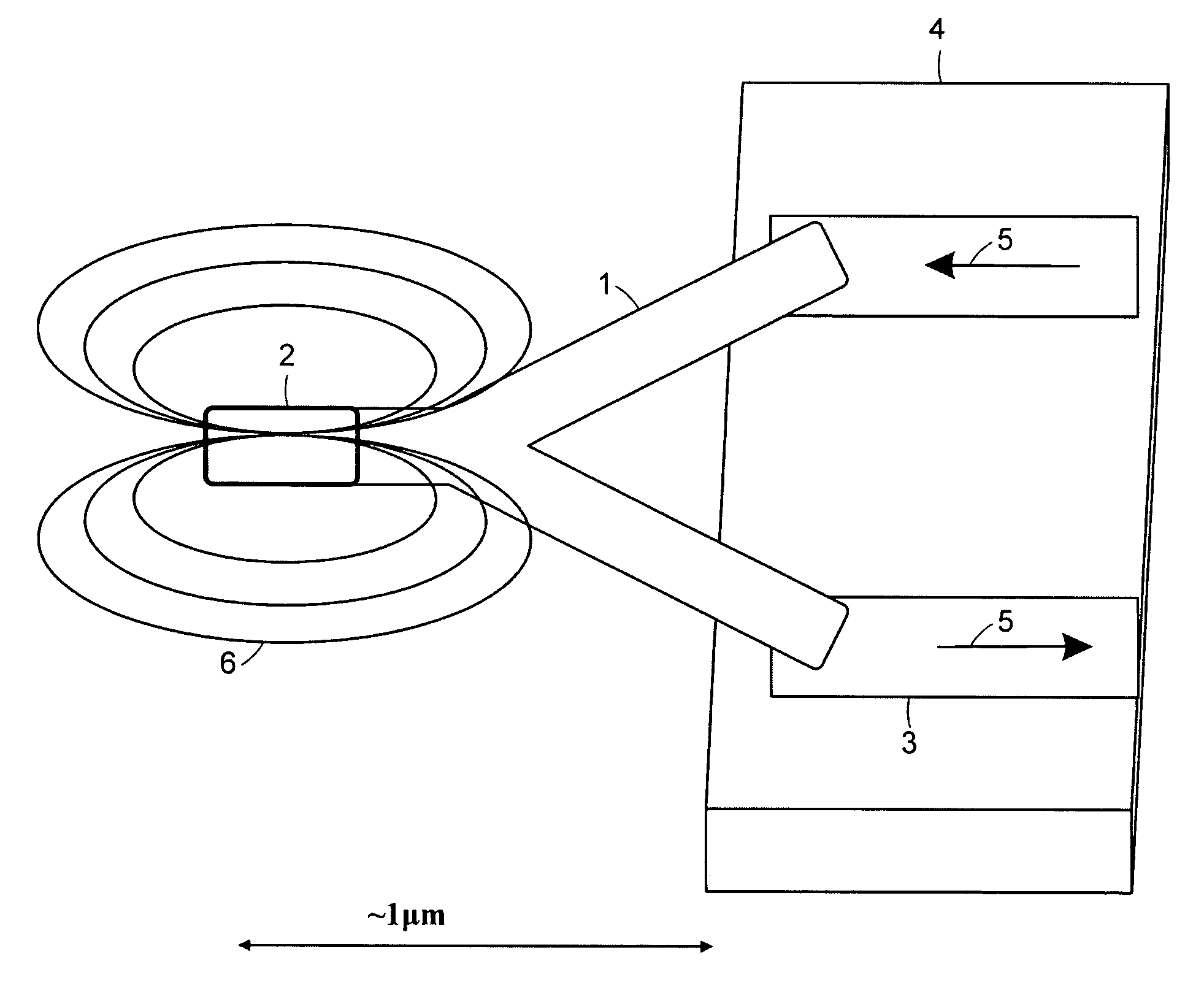
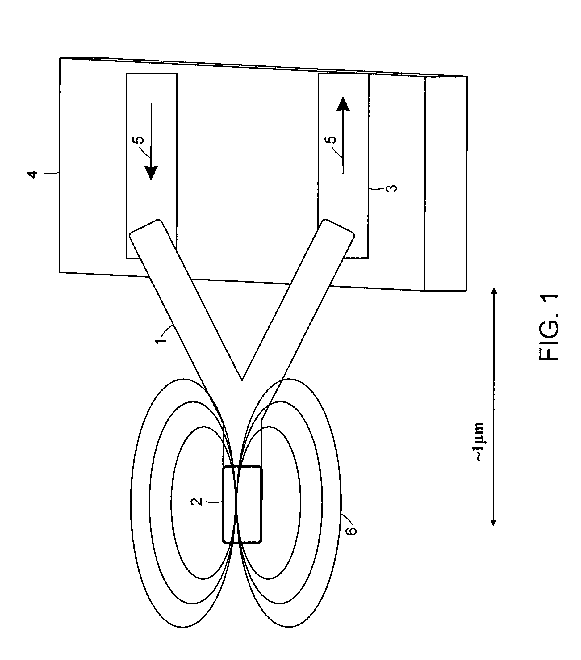
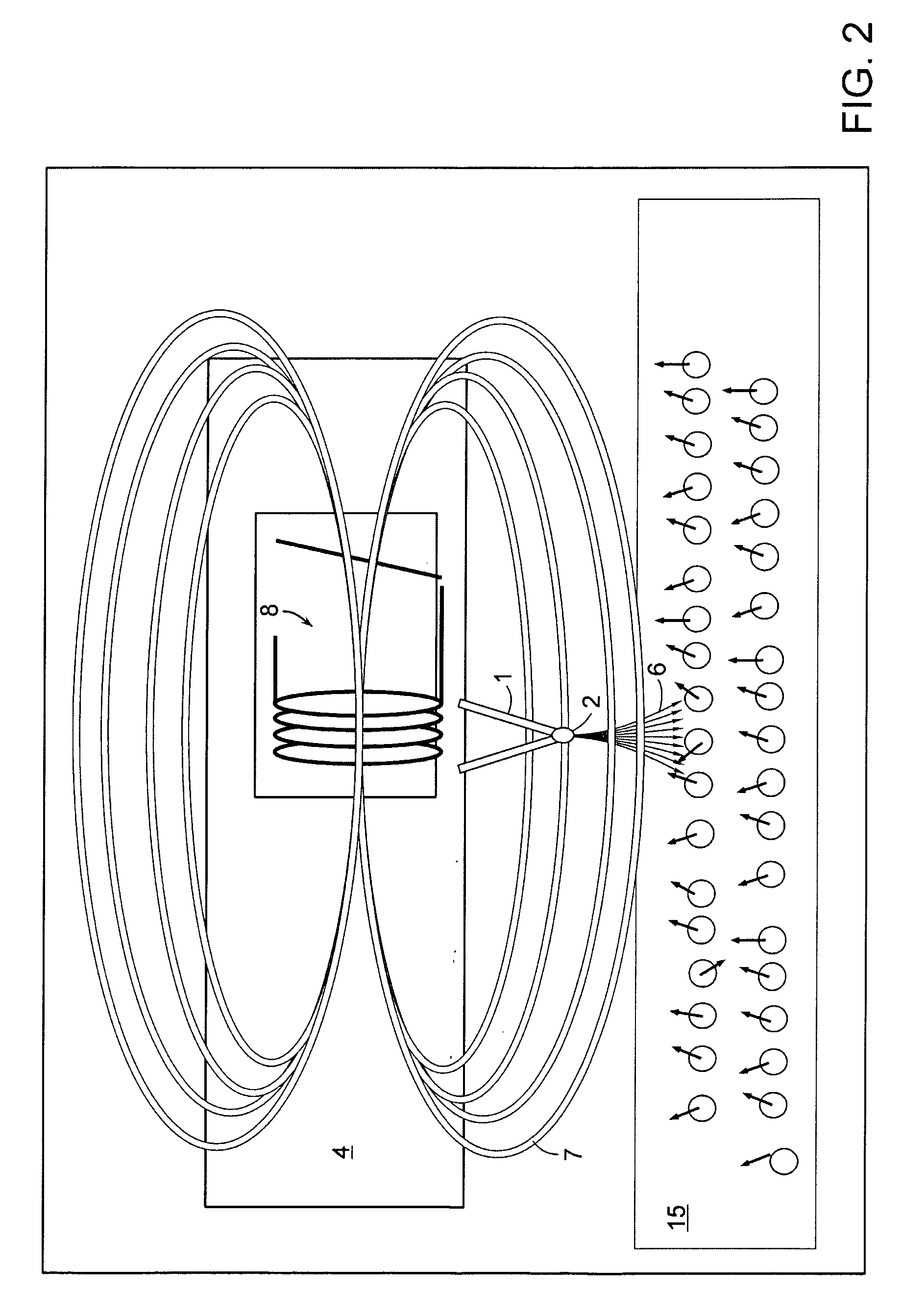
Cantilever probes for nanoscale magnetic and atomic force microscopy
a microscopy and magnetic field technology, applied in the field of microdimensional analytical probes, can solve the problems of inability to use present cantilevers, the difficulty of optical detection, and the inability to detect single proton and single electron spin of micro-dimensional probes
- Summary
- Abstract
- Description
- Claims
- Application Information
AI Technical Summary
Benefits of technology
Problems solved by technology
Method used
Image

Examples
example 1
Preparation of Catalyst Substrate for Synthesis of Linear CNTs
[0089]Mesoporous silica containing iron nanoparticles were prepared by a sol-gel process by hydrolysis of tetraethoxysilane (TEOS) in the presence of iron nitrate in aqueous solution following the method described by Li et al. (Science, (1996), Vol. 274, 1701–3) with the following modification. The catalyst gel was dried to remove excess water and solvents and calcined for 10 hours at 450° C. and 10−2 torr to give a silica network with substantially uniform pores containing iron oxide nanoparticles that are distributed within. The catalyst gel is then ground into a fine, micro-particulate powder either mechanically using a ball mill or manually with a pestle and mortar. The ground catalyst particles provide particle sizes that range between 0.1 and 100 μM under the grinding conditions.
example 2
Preparation of Catalyst Substrate for Synthesis of Branched CNTs
[0090]Catalyst substrates were prepared following the method described by Li et al. (Applied Physics Letters (2001) Vol. 79(12), 1879–1881). Magnesium oxide (MgO) supported cobalt (Co) catalysts were prepared by dissolving 0.246 g of cobalt nitrate hexahydrate (Co(NO3)2.6H2O, 98%) in 40 ml ethyl alcohol, following immersing 2 g of particulate MgO powder (−325 mesh) were added to the solution with sonication for 50 minutes. The solid residue was filtered, dried and calcined at 130° C. for 14 hours.
example 3
General Synthetic Procedure for Branched CNTs
[0091]The MgO supported cobalt catalyst of Example 2 were first reduced at 1000° C. for 1 hour in a pyrolytic chamber under a flow of a mixture hydrogen (40 sccm) and nitrogen (100 sccm) at a pressure of 200 Torr. The nitrogen gas was subsequently replaced with methane (10 sccm) to initiate CNT growth. The optimum reaction time for producing branched CNTs was 1 hour.
PUM
| Property | Measurement | Unit |
|---|---|---|
| diameter | aaaaa | aaaaa |
| diameters | aaaaa | aaaaa |
| diameters | aaaaa | aaaaa |
Abstract
Description
Claims
Application Information
 - R&D
- Intellectual Property
- Life Sciences
- Materials
- Tech Scout
- Unparalleled Data Quality
- Higher Quality Content
- 60% Fewer Hallucinations
Browse by: Latest US Patents, China's latest patents, Technical Efficacy Thesaurus, Application Domain, Technology Topic, Popular Technical Reports.
© 2025 PatSnap. All rights reserved.Legal|Privacy policy|Modern Slavery Act Transparency Statement|Sitemap|About US| Contact US: help@patsnap.com