Pattern method and system for detecting foreign object debris

a technology for foreign objects and patterns, applied in the field of object detection methods, can solve the problems of difficult detection of fod, human error, and decrease in the safety of the aircraft, and achieve the effects of reducing the amount of average power consumed, reducing eyestrain, and reducing potential generation

Inactive Publication Date: 2007-05-08
THE BOEING CO
View PDF25 Cites 10 Cited by
  • Summary
  • Abstract
  • Description
  • Claims
  • Application Information

AI Technical Summary

Benefits of technology

[0011]Another advantage of the present invention is that it provides an efficient method for detecting non-fixed objects within an aircraft.
[0012]Furthermore, the present invention provides a system that is capable of detecting non-fixed objects within areas that were traditionally difficult to access.
[0013]Moreover, the present invention synchronizes light from the object illuminator with the detector observing reflected light from the light emitting or generating substance. In so doing the present invention minimizes eyestrain, ocular fluorescence, and amount of average power consumed by the object illuminator, which in effect also reduces potential generation of a large heat load. By minimizing eyestrain and ocular fluorescence, a user's ability to detect FOD is increased. Also, the present invention by synchronizing light generation, a decreased frequency range of ultraviolet light is utilized allowing use of ultraviolet light frequencies that are relatively less harmful to a human eye.
[0014]In accordance with the above and other advantages of the present invention, production costs of an aircraft are reduced. Costs are reduced directly due to decreased time and energy in searching for non-fixed objects. Costs are also reduced indirectly as a result of potential decreases in post manufacturing costs due to aircraft malfunction caused by non-fixed objects going undetected. Aircraft quality and safety are also improved by increasing the probability that difficult to locate FOD will be identified.
[0015]The present invention itself, together with other attendant advantages, will be best understood by reference to the following detailed description, taken in conjunction with the accompanying figures.

Problems solved by technology

An unknown loose object on board an aircraft may cause an aircraft to malfunction or not operate as designed thereby decreasing safety of the aircraft.
FOD are difficult to detect and many hours of searching for FOD occur during production of an aircraft, to assure the aircraft is free from loose objects, before the aircraft leaves a production facility or is operated.
Moreover, because the detection of FOD relies almost solely on visual inspection, it can be subject to human error.
Furthermore, confined nature of an aircraft structure hinders vehicle through inspection.
A large aircraft has various cavities, pockets, and crevices that cause the process of detecting FOD to be difficult.
The larger the amount of undetected FOD the increased likelihood of an aircraft system malfunctioning.
As known in the art and as taught by Garrity, in order to properly install a supplemental restraining device, such as a lock-wire, to a component, the component must be fixed, otherwise the supplemental restraining device does not serve its intended purpose.
Garrity unfortunately, is only directed at fixed components, on a gas turbine engine, that require proper installation of a supplemental restraining device as to prevent the components from becoming unfastened.
There are associated disadvantages with known FOD detecting methods.
One disadvantage is that during inspection of an aircraft for FOD, using the known FOD detecting methods, some inspection areas can exist that are difficult to access or view and in some situations at least to some extent can not be inspected.
Another disadvantage with exiting methods is that by continuously detecting FOD using an ultraviolet light source, eyestrain or ocular fluorescence can result that can lower a users ability to detect FOD.
Furthermore, use of an ultraviolet lamp can be hazardous when there are defects in filters of existing FOD detecting systems that are used to eliminate more harmful ultraviolet wavelengths.
Yet another disadvantage is that the existing systems use ultraviolet lamps that are large and can consume approximately 100 watts of power, thus generating a heat load and a potential burn or fire hazard.

Method used


Image

  • Pattern method and system for detecting foreign object debris
  • Pattern method and system for detecting foreign object debris
  • Pattern method and system for detecting foreign object debris

Examples


Embodiment Construction

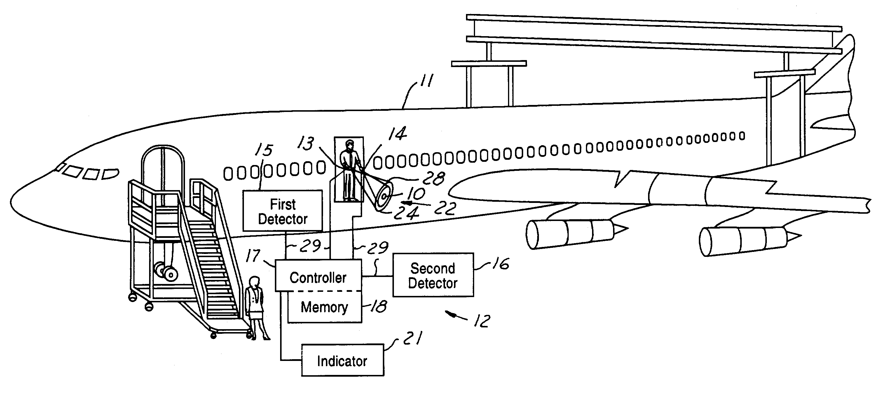
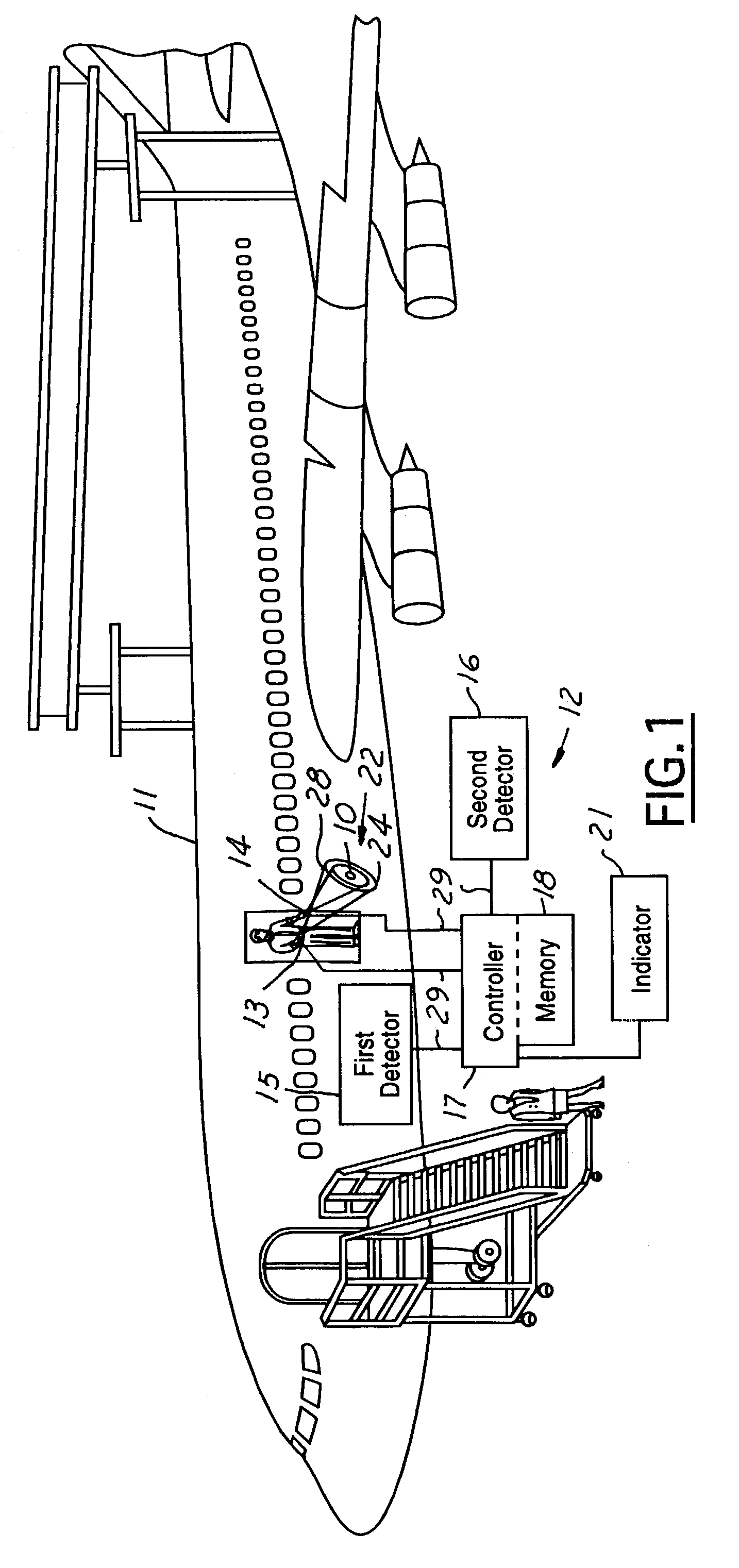
[0020]While the present invention is described with respect to a method and system for detecting non-fixed objects within an aircraft, the present invention may be adapted to be used for a variety of other components and systems including automotive vehicles, electronic or mechanical systems, machinery, or other components or systems that may require detection of a non-fixed object. The present invention may also be used in various production and manufacturing processes including before, during, and after assembly of a system. The present invention may also be applied in various types of inspection, such as in dye penetrant inspection of raw materials. In the following description, various operating parameters and components are described for one constructed embodiment. These specific parameters and components are included as examples and are not meant to be limiting.

[0021]Referring now to FIG. 1, a representative illustration of implementing a method of detecting a non-fixed object...


PUM

PropertyMeasurementUnit
wavelengthaaaaaaaaaa
fluorescence wavelengthsaaaaaaaaaa
absorption frequency rangeaaaaaaaaaa

Abstract

A method of detecting a non-fixed object in a system (12) includes applying a light emitting or generating substance to multiple objects. The objects are illuminated with an object illuminator (13). At least one of the objects (10) is determined to be a nonmember within a known pattern of objects and is identified to be a non-fixed object in response to illumination of the objects.

Description

RELATED APPLICATION[0001]The present application is a continuation-in-part (CIP) application of U.S. patent application Ser. No. 09 / 954,404 filed Sep. 17, 2001 entitled “A METHOD FOR DETECTING FOREIGN OBJECT DEBRIS”, which is incorporated by reference herein.TECHNICAL FIELD[0002]The present invention relates generally to object detection methods, and more particularly to a method and system for detecting foreign object debris on an aircraft.BACKGROUND OF THE INVENTION[0003]Aircraft safety is an ongoing concern for aircraft producers. An unknown loose object on board an aircraft may cause an aircraft to malfunction or not operate as designed thereby decreasing safety of the aircraft. Unknown loose objects are referred to as foreign object debris (FOD) in the art. FOD are difficult to detect and many hours of searching for FOD occur during production of an aircraft, to assure the aircraft is free from loose objects, before the aircraft leaves a production facility or is operated. More...

Claims


Application Information

Patent Timeline
Patent Type & Authority Patents(United States)
IPC IPC(8): G01N21/64B64F5/00
CPCB64F5/0018B64F5/0045G01N21/643G01N21/6447B64F5/30B64F5/60
Inventor WAGONER, DANIEL E.TAYLOR, MICHAEL L.CLAYTON, JOHN C.FITTS, JOHN D.BENFER, GREG L.JOHNSON, LYNN E.SPENO, FRANK G.
Owner THE BOEING CO
Why Eureka
Try Eureka