
Duobinary optical transmitter

a technology of optical transmitters and binaries, applied in the field of optical communication systems, can solve the problems of increasing the manufacturing cost affecting the cost competitiveness of the entire optical transmitter, and generating code interference, so as to improve the cost competitiveness and reduce the bandwidth

Inactive Publication Date: 2007-05-08
SAMSUNG ELECTRONICS CO LTD
View PDF6 Cites 11 Cited by
  • Summary
  • Abstract
  • Description
  • Claims
  • Application Information

AI Technical Summary

Benefits of technology

[0012]One aspect of the present invention is to provide a duobinary optical transmitter capable of allowing improved cost competitiveness by using components having a lower bandwidth.

Problems solved by technology

Due to an excessive limitation on the bandwidth, an interference among codes is generated.
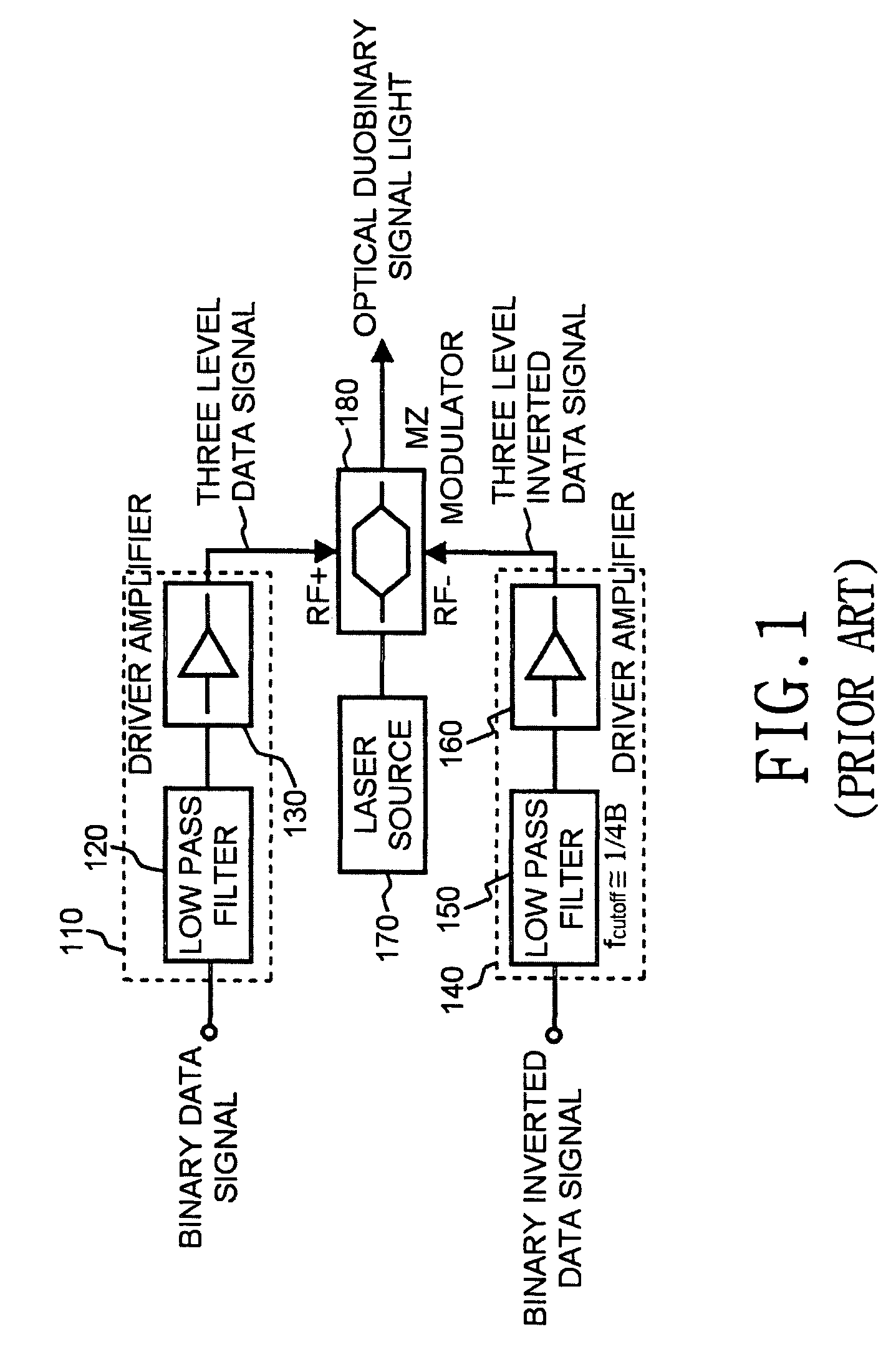
The remaining modulator driver and optical intensity modulator both have a bandwidth corresponding to a clock frequency of the two-level binary signal and tend to be expensive to implement.
Accordingly, the conventional transmitter has a drawback in that using devices of high bandwidth increases the manufacturing cost of the entire optical transmitter, and therefore the cost competitiveness of the optical transmitter is weakened.

Method used


Image

  • Duobinary optical transmitter
  • Duobinary optical transmitter
  • Duobinary optical transmitter

Examples


Embodiment Construction

[0020]Hereinafter, duobinary optical transmitters according to preferred embodiments of the present invention will be described with reference to the accompanying drawings. For the purposes of clarity and simplicity, a detailed description of known functions and configurations incorporated herein will be omitted as it may make the subject matter of the present invention unclear.

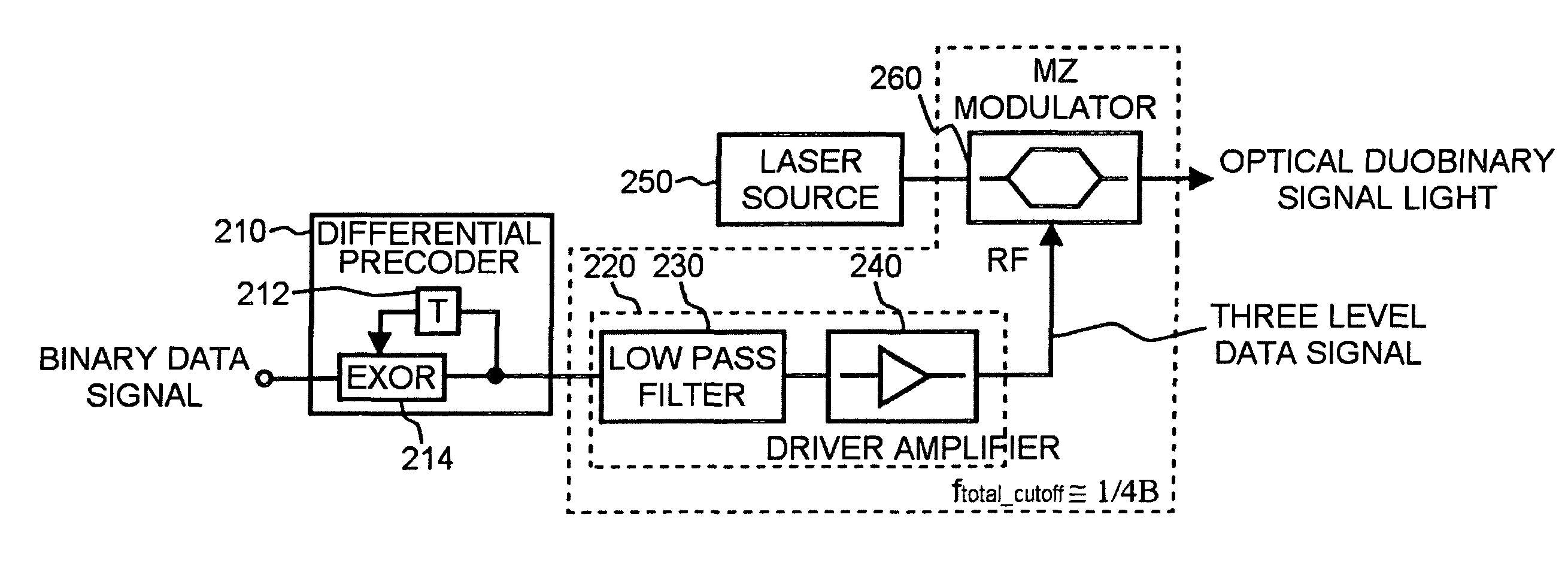
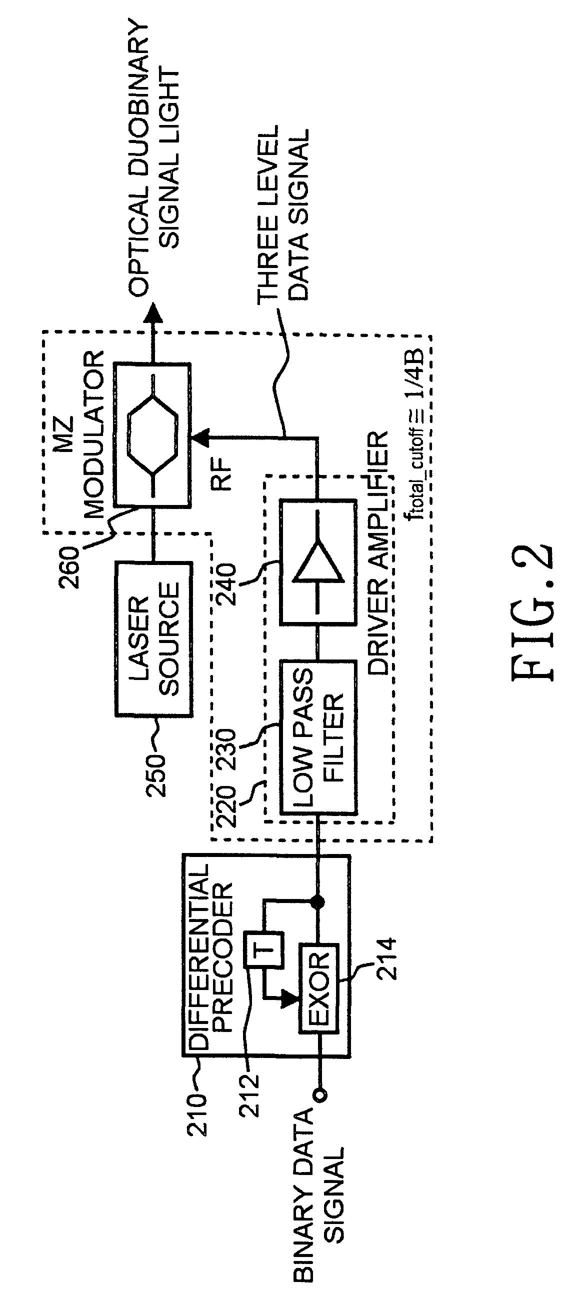
[0021]FIG. 2 shows the configuration of a duobinary optical transmitter according to the embodiment of the present invention. The inventive transmitter includes a differential precoder 210; a low-pass filter 230; a modulator driver / amplifier 240; a laser source 250; and, a Mach-Zehnder interferometer-type optical intensity modulator 260. The low-pass filter 230 and the modulator driver 240 constitute an arm 220, which is in turn connected to a modulation terminal (RF) of the optical intensity modulator 260.

[0022]The differential precoder 210 comprises a one-bit delay line 212 and an EXOR (Exclusive OR) circui...


PUM


Abstract

Disclosed is a duobinary optical transmitter, which includes a laser source for outputting light with a predetermined wavelength; a Mach-Zehnder interferometer-type optical intensity modulator for modulating the intensity of the light according to a three-level data signal inputted through a modulation terminal; a low-pass filter for converting an inputted two-level binary data signal into a three-level data signal through an interference among codes; and, a modulator driver / amplifier for amplifying the three-level data signal and then outputting it to the modulation terminal, wherein the overall bandwidth of the low-pass filter, the modulator driver / amplifier, and the optical intensity modulator corresponds to approximately ¼ of the clock frequency of the two-level binary data signal.

Description

CLAIM OF PRIORITY[0001]This application claims priority to an application entitled “duobinary optical transmitter,” filed with the Korean Intellectual Property Office on Oct. 11, 2002 and assigned Serial No. 2002-62162, the contents of which are hereby incorporated by reference.BACKGROUND OF THE INVENTION[0002]1. Field of the Invention[0003]The present invention relates to an optical communication system and, more particularly to an optical transmitter for generating optical signals.[0004]2. Description of the Related Art[0005]Optical communication systems utilizing a Dense-Wavelength-Division-Multiplexing (DWDM) scheme have an excellent communication efficiency as they permit the transmission optical signals of multiple channels with different wavelengths through a single optical fiber. The DWDM systems can also transmit optical signals having different transmission speeds. As such, the DWDM are now widely used in ultra-high speed Internet networks, and systems capable of transmitt...

Claims


Application Information

Patent Timeline
IPC IPC(8): H04B10/04G02F1/03H04B10/516H04B10/54H04B10/556H04B10/588H04B10/61
CPCH04B10/505H04B10/5055H04B10/5167H04B10/50H04B10/516H04B10/2581
Inventor LEE, HAN-LIMHWANG, SEONG-TAEKCHEUNG, HEE-WONOH, YUN-JEJEONG, JI-CHAIKANG, BYUNG-CHANG
Owner SAMSUNG ELECTRONICS CO LTD
Learn More