Differential motion conveyor

a technology of conveyors and shafts, applied in conveyors, conveyors, jigging conveyors, etc., can solve the problems of inability to achieve the modest throughput capability of conveyors, failure at an inopportune time, and inefficiency of feed ra

Active Publication Date: 2007-05-15
PPM TECH HLDG LLC
View PDF9 Cites 23 Cited by
  • Summary
  • Abstract
  • Description
  • Claims
  • Application Information

AI Technical Summary

Problems solved by technology

Intuitively, higher cycle speeds should yield higher feed rates, but then the conveyor becomes more sensitive to changing velocity patterns, resulting in greater accelerations than may be desired during some of the conveying portion of the cycle, resulting in feed rate inefficiencies.
As a result, some materials feed better than others, but the coefficients of friction typically are not a major influence on the potential feed rate capabilities of the conveyor.
The limiting factors on stroke include mechanical and dynamic design considerations, power usage requirements, isolation efficiency, and overall cycle speed control capability.
One drawback to “four shaft” conveyor drives is their high cost relative to the modest throughput capabilities obtained.
Ongoing preventative maintenance is a must since, like any other machine having belts, gears, bearings and other wear parts, they might fail at an inopportune time.
However, this construction may be limited in size due to scale up constraints, and it requires the use of a hydraulic brake damper to eliminate inertial load backlash at the speed transition points.
The potential problem of a hydraulic oil leak in a food-handling environment from a sanitary perspective is undesirable.
Hydraulic fluids and gear oil required for this drive also raises sanitary installation issues in food handling environments.
This type of conveyor also requires that the base members be solidly connected to the floor, making suspension mounting difficult or ruling it out as an installation option.
The linear motor disclosed in this patent is relatively complex, is relatively expensive to make, and requires relatively high input power to operate, at an ongoing higher operating expense.
Also, the cranks, crank assemblies, linkages and multiple counterweights compensating for unwanted vibration and noise are costly to manufacture and costly to maintain.
Further, it would not be practical to suspend the apparatus, as it must be connected to a firm foundation to operate correctly.
It may also be difficult to reverse the direction of feed of the conveyor by simply inverting the motion pattern due to the complex nature of the counterbalance system.
This design does not address the issues of product feed rate optimization, suspension mounting of the conveyor, or simple reversal of feed direction of the conveyed product.
Although the transitions between clutch / brake engagement and disengagement may be made smoother by allowing some slippage as the electromagnetic field is turned on and off to the clutch / brake, the machine essentially operates at two speeds and may not be able to generate the most efficient differential motion velocity patterns for optimum feed rate.
Also, the conveyor would be difficult to suspend, since a solid mounting foundation is required.
In addition, the required spring system might make the design more costly to manufacture and sell.

Method used


Image

  • Differential motion conveyor
  • Differential motion conveyor
  • Differential motion conveyor

Examples


Embodiment Construction

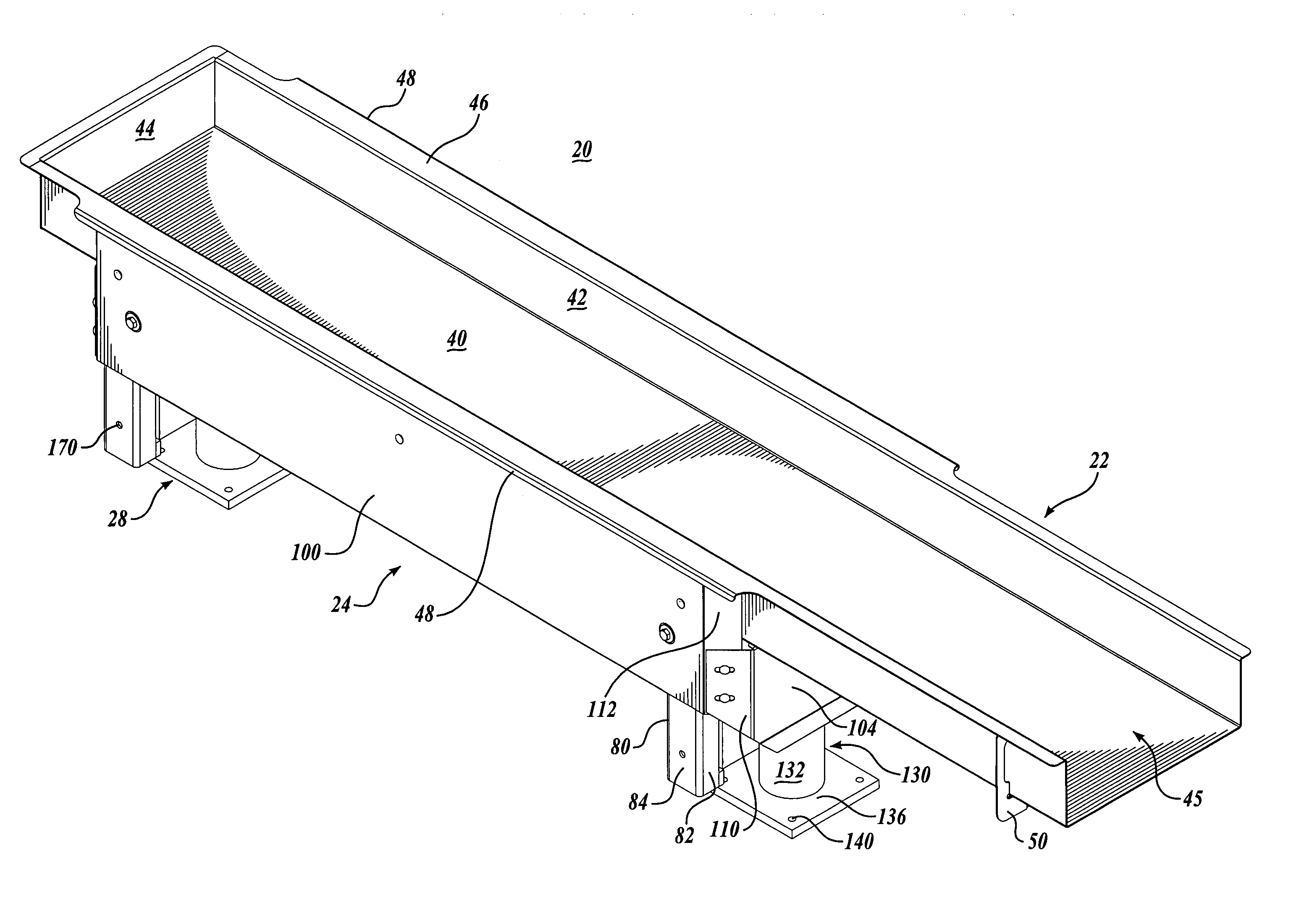
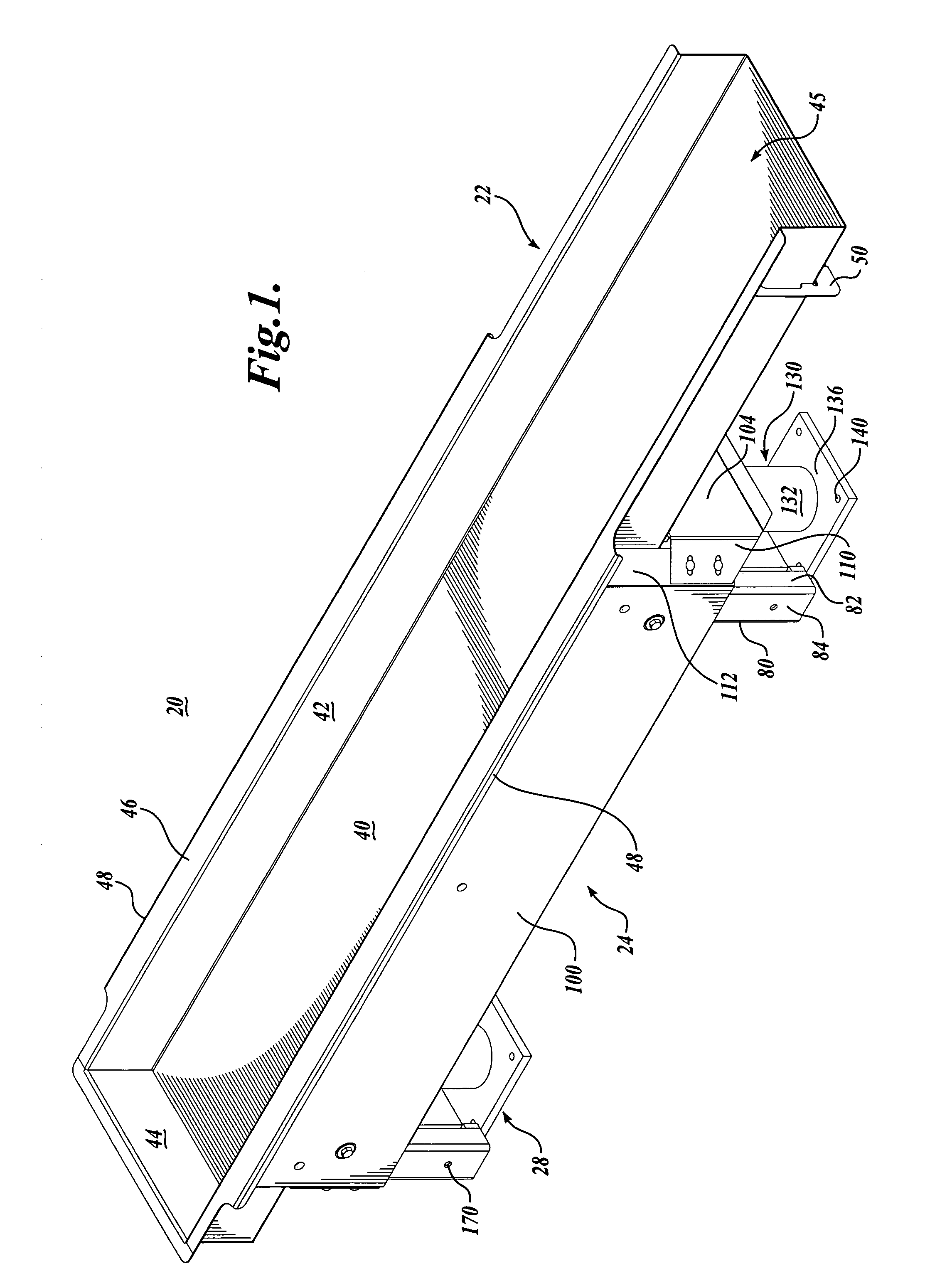
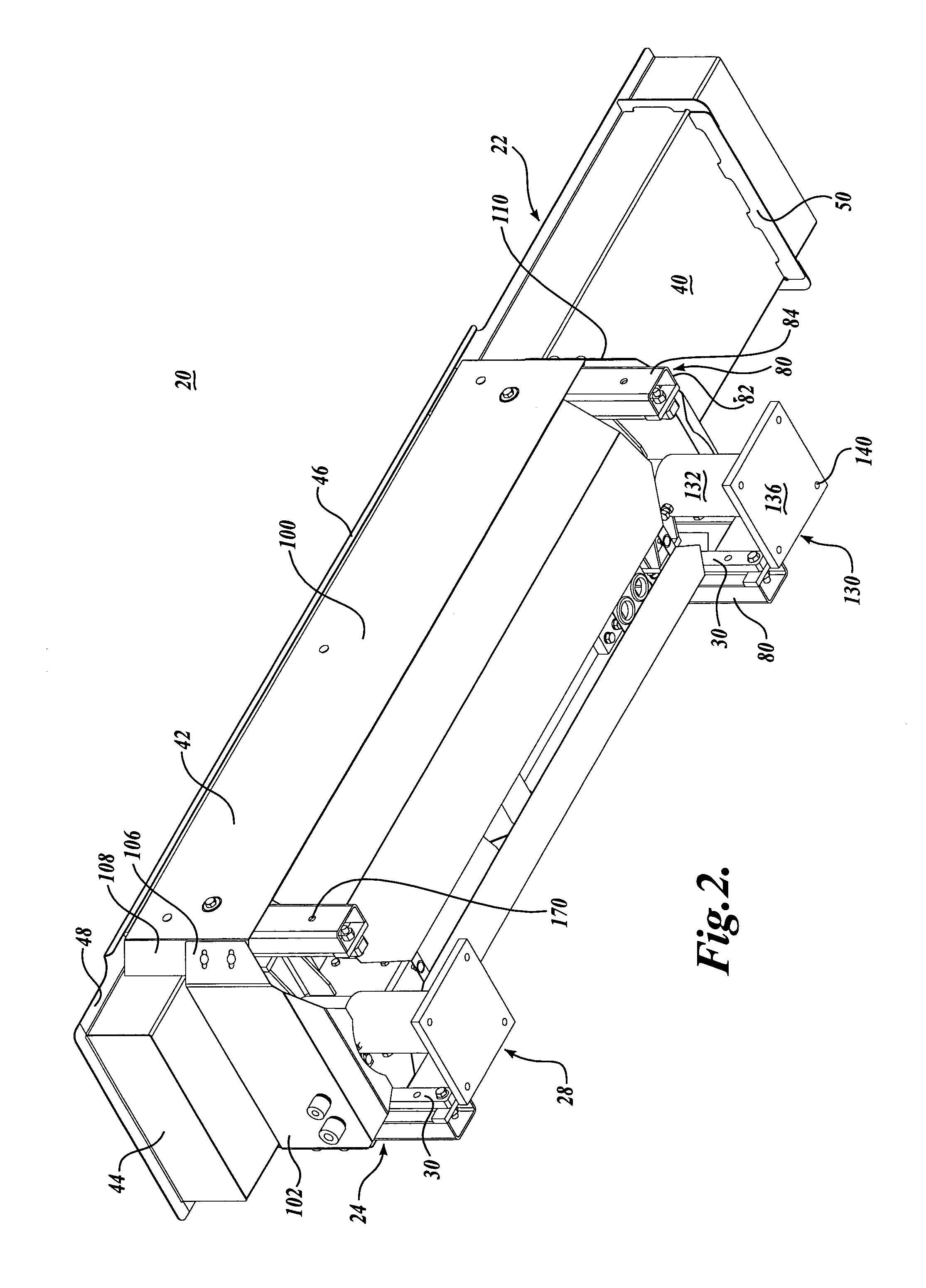
[0040]Referring initially to FIGS. 1 through 4, conveyor 20 is illustrated as composed of an elongate trough structure 22 adapted to longitudinally reciprocate relative to a counterweight base structure 24 through a servo motor drive system 26. The base structure 24 is supported by a floor engaging stand or support frame 28 so as to be able to swing or reciprocate back and forth relative to the support frame by the use of a plurality of hanging swing arms 30 pivotally interconnected between the base structure and frame.

[0041]Next, describing the construction and operation of the present invention in greater detail, the trough structure 22 includes an elongated, flat pan 40 with upright sidewalls 42 and an upright end wall 44 at one end of the trough. One end of the trough 22 is closed off by end wall 44, while the opposite end 45 of the trough is illustrated as open. A top flange extends laterally outwardly from the upper edge of the sidewalls 42 and end wall 44 to add stiffness to ...


PUM


Abstract

A differential motion conveyor (20) for conveying products along an elongated trough structure (22) supported for reciprocal movement relative to a counterweight base structure (24) of a weight significantly greater than the weight of the trough structure. A rotational actuator (200) moving in a singular direction reciprocates the trough structure lengthwise relative and counterweighed base structure at a substantially continually varying velocity of the actuator to achieve a desired differential acceleration rate of the trough structure between the two opposing directions of longitudinal movement of the trough structure.

Description

FIELD OF THE INVENTION[0001]The invention relates to differential motion conveyors used to convey bulk materials. In particular, the invention relates to differential motion conveyors utilizing a servo motor drive system.BACKGROUND OF THE INVENTION[0002]Differential motion conveyors are used to convey many types of products, for example, snack foods or the like. Snack food manufacturers may utilize differential motion conveyors to convey product from cooking process equipment to packaging equipment. Differential motion conveyors employ conveying forces having substantially only horizontal components unlike vibratory conveyors in which the conveying forces have both horizontal and vertical components. Since little or no vertical force components exist, it is generally perceived that differential motion conveyors handle fragile material such as snack foods in a gentler manner and therefore have less product breakage and build-up of food particles or flavoring material on the conveying...

Claims


Application Information

Patent Timeline
Patent Type & Authority Patents(United States)
IPC IPC(8): B65G25/04
CPCB65G27/30B65G27/32
Inventor PATTERSON, HAROLD E.SLEPPY, PAULMARTIN, LARRY D.
Owner PPM TECH HLDG LLC
Why Eureka
Try Eureka