Cooling fluid preheating system for an airfoil in a turbine engine

a technology of cooling fluid and airfoil, which is applied in the direction of liquid fuel engines, vessel construction, marine propulsion, etc., to achieve the effect of reducing the temperature gradient that develops in the airfoil and reducing the thermal stress in the airfoil

Active Publication Date: 2007-05-15
SIEMENS ENERGY INC
View PDF13 Cites 23 Cited by
  • Summary
  • Abstract
  • Description
  • Claims
  • Application Information

AI Technical Summary

Benefits of technology

[0006]This invention relates to a preheating system for cooling fluids in an airfoil of a turbine engine. The invention also relates to use of the preheating system to form a serial cooling system for a composite turbine airfoil in which the preheating system in the platform and a cooling system in the airfoil form a continuous cooling system not supplemented with additional cooling fluids along the cooling system from a first end of the preheating system in the platform to an exhaust of the cooling system in the airfoil. By preheating the cooling fluids in the platform of an airfoil, the temperature gradient that develops in the airfoil is reduced, thereby reducing the thermal stresses in the airfoil.
[0007]In at least one embodiment, the cooling fluid preheating system is a platform cooling system positioned in one or more platforms of an airfoil for heating cooling fluids before the cooling fluids enter an internal cooling system in inner aspects of the airfoil. The platform cooling system may be formed from one or more channels in the first platform that are in communication with the cooling system in the elongated airfoil. Heat is removed from the platform and used to heat the cooling fluids passing through the channels in the platform forming the cooling fluid preheating system. The platform cooling system is particularly suited for use with composite airfoils, such as, but not limited to ceramic matrix composites, to reduce the temperature gradients between outer surfaces of an airfoil and inner cooling channels to reduce the risk of delamination and other failure of the airfoil.
[0013]By preheating the cooling fluids in the platform, the temperature gradient that exists between the outer surface of the airfoil and the inner surfaces of the airfoil cooling channels is reduced when compared with conventional cooling systems. The reduction in the temperature gradient between outside surfaces of the airfoil and the cooling fluids in the cooling channels in the airfoil advantageously reduces the thermal stress encountered by the airfoil and therefore, increases the life of the airfoil. Such stress reduction increases the viability of use of composite blades in turbine engines.
[0014]An advantage of this invention is that the platform cooling system greatly reduces the temperature gradient across an airfoil in a turbine engine, and thus, reduces the thermal stress in the airfoil as well. The reduction in thermal stress is particularly advantageous for composite airfoils that are susceptible to damage, such as delamination between layers and destruction of bonds, resulting from temperature gradients.
[0015]Another advantage of this invention is that the platform cooling system makes use of airfoils formed from composite materials more viable by reducing the thermal stresses that damage composite materials. Because composite airfoils can withstand higher temperatures than conventional metals used to form airfoils, less cooling fluids are needed in composite airfoils. In fact, use of composite airfoils may reduce the total cooling fluid flow requirement by approximately 90 percent. Such a reduction in cooling fluid flow can greatly improve the efficiency of the gas turbine engine in which the platform cooling system is installed.

Problems solved by technology

In addition, turbine airfoils often contain internal cooling systems for prolonging the life of the airfoils and reducing the likelihood of failure as a result of excessive temperatures.

Method used


Image

  • Cooling fluid preheating system for an airfoil in a turbine engine
  • Cooling fluid preheating system for an airfoil in a turbine engine
  • Cooling fluid preheating system for an airfoil in a turbine engine

Examples


Embodiment Construction

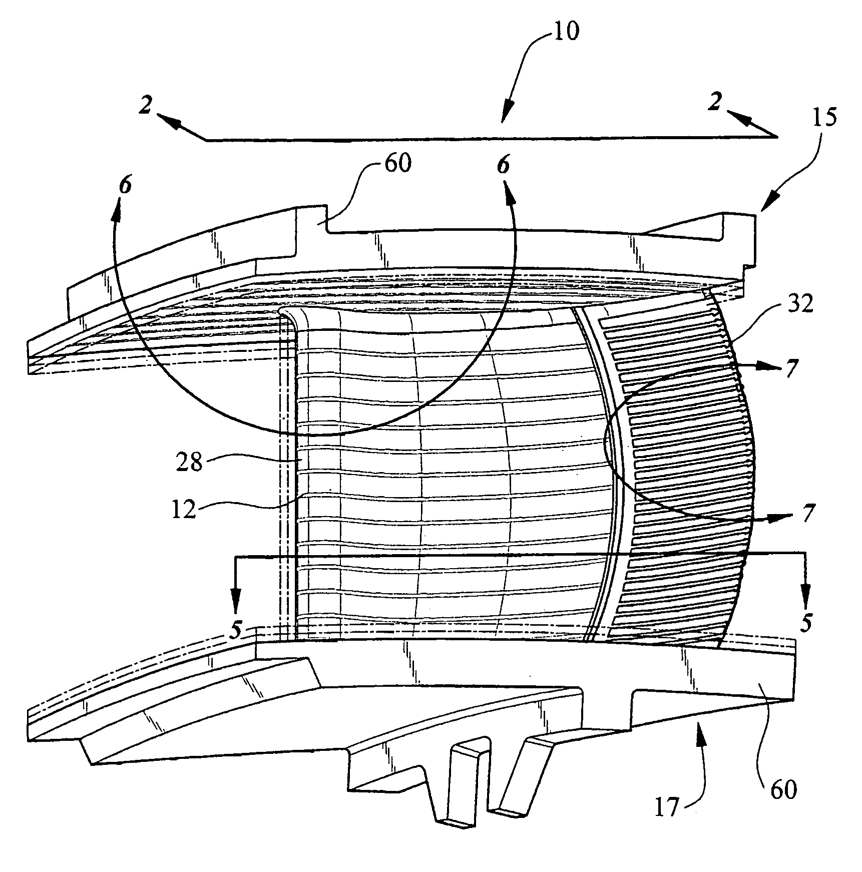
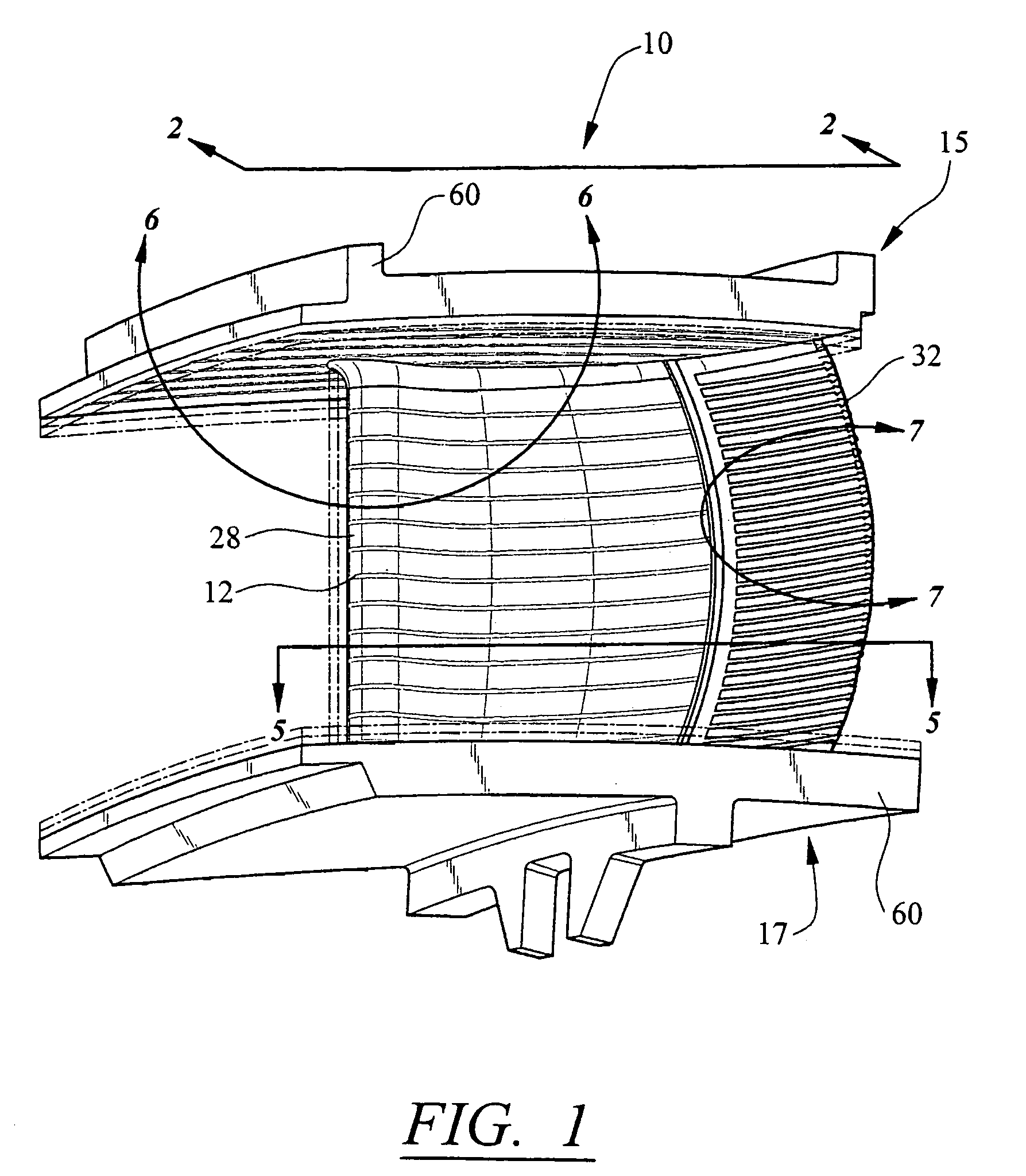
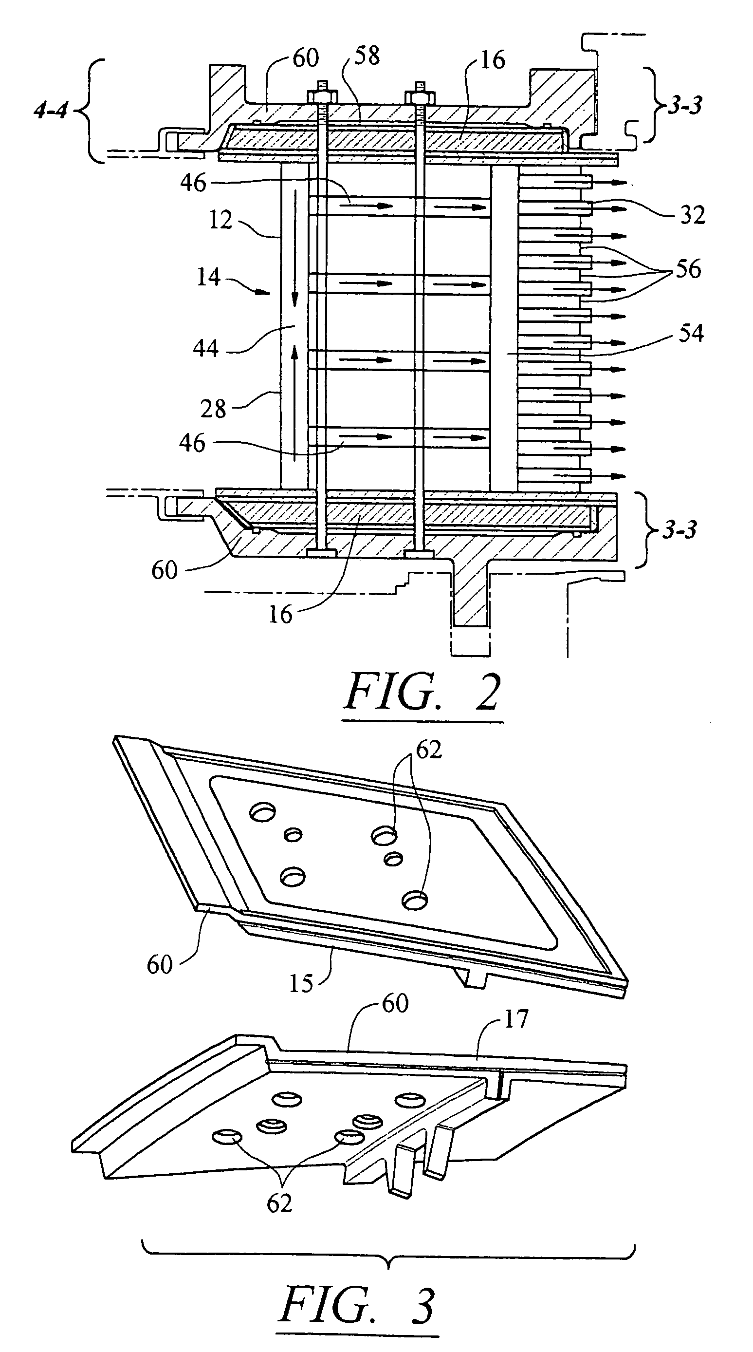
[0025]As shown in FIGS. 1–7, this invention is directed to a platform cooling system 10 usable to preheat cooling fluids in a turbine engine. The platform cooling system 10 is particularly useful in composite airfoils 12 in which temperature gradients cause layers of the airfoil 12 to delaminate and bonds between adjacent layers to break. In addition, the platform cooling system 10 may be incorporated with an internal cooling system 14 in the airfoil 12 such that the airfoil is cooled with cooling air in a serial cooling manner such that cooling fluids passed through the platform cooling system 10 flow through the airfoil 12 without being supplemented by lower temperature cooling air while in the airfoil 12.

[0026]The platform cooling system 10 may receive cooling fluids from a compressor (not shown) or other source, increase the temperature of the cooling fluids, and pass the cooling fluids on to a cooling system 14 in the airfoil 12 with a temperature that is greater than a tempera...


PUM


Abstract

A platform cooling system usable in a turbine engine together with an airfoil for preheating cooling fluids before the cooling fluids enter a cooling system in the airfoil in a turbine engine. The platform cooling system includes cooling channels in either the ID or OD platforms, or both, of the airfoil. The channels transfer heat to the cooling fluids flowing through the platform cooling system and thereby heat the cooling fluids. The preheated cooling fluids are particularly useful with cooling composite ceramic airfoils, which are susceptible to damage from large temperature gradients developed between combustion gases outside the airfoil and cooling fluids inside the airfoil. The platform cooling system may be combined with an airfoil cooling system to create a serial cooling system in which cooling fluids may enter the platform and flow through the platform and airfoil without being supplemented with additional cooling fluids along the flow path.

Description

FIELD OF THE INVENTION[0001]This invention is directed generally to airfoils in turbine engines, and more particularly to airfoils having a need for reduced temperature gradients within the airfoil, such as composite airfoils.BACKGROUND[0002]Typically, gas turbine engines include a compressor for compressing air, a combustor for mixing the compressed air with fuel and igniting the mixture, and a turbine blade assembly for producing power. Combustors often operate at high temperatures that may exceed 2,500 degrees Fahrenheit. Typical turbine combustor configurations expose turbine vane and blade assemblies, to these high temperatures. As a result, turbine airfoils, such as turbine vanes and blades must be made of materials capable of withstanding such high temperatures. In addition, turbine airfoils often contain internal cooling systems for prolonging the life of the airfoils and reducing the likelihood of failure as a result of excessive temperatures.[0003]Typically, turbine airfoi...

Claims


Application Information

Patent Timeline
Patent Type & Authority Patents(United States)
IPC IPC(8): F03B11/02
CPCF01D5/18F05D2260/205F05D2240/81F05D2300/603
Inventor ALBRECHT, HARRY A.SHTEYMAN, YEVGENIY
Owner SIEMENS ENERGY INC
Why Eureka
Try Eureka