Turbine rotor blade for gas turbine engine

a technology of turbine rotor blades and turbine engines, which is applied in the direction of marine propulsion, vessel construction, other chemical processes, etc., can solve the problems of high reliability and low manufacturing cost, and achieve the effect of uniformly redistributing the aerodynamic load

Inactive Publication Date: 2007-05-15
ANSALDO ENERGIA SWITZERLAND AG
View PDF9 Cites 25 Cited by
  • Summary
  • Abstract
  • Description
  • Claims
  • Application Information

AI Technical Summary

Benefits of technology

[0013]Accordingly, the technical problem to be solved by the present invention is to provide a turbine rotor blade for a gas turbine engine which avoids the drawbacks of the cited prior art but still provides reduced tip leakage losses. Further, the manufacturing costs should be kept low and the reliability high.
[0019]The terms “concave” and “convex” refer in this context to the chordwise direction. Preferably, the increase in stagger is such as to give rise to chord-wise convex curvature on the pressure surface. This has the aerodynamic result that velocities on the pressure surface are increased, reducing the local static pressure which drives the over-tip leakage, thus reducing the leakage further.
[0022]The lower part of the aerofoil will exemplarily have a minimum radial extent of 40% and a maximum radial extent of 80% of the span. The tip section is preferably geometrically and aerodynamically blended smoothly into the lower portion of the aerofoil. The blending of the aerofoil between the tip section and the lower portion will preferably be such as to evenly redistribute the aerodynamic loading radially away from the tip.

Problems solved by technology

Further, the manufacturing costs should be kept low and the reliability high.

Method used


Image

  • Turbine rotor blade for gas turbine engine
  • Turbine rotor blade for gas turbine engine
  • Turbine rotor blade for gas turbine engine

Examples


Embodiment Construction

[0042]Before describing in detail the geometric configuration of a turbine rotor blade in accordance with the invention, it is useful to describe how the configuration operates, and in particular how it affects the turbine rotor aerodynamics. First the basic turbine aerodynamics will be considered, then the benefits of aerodynamically off-loading the tip, and finally the detail of the invention will be described.

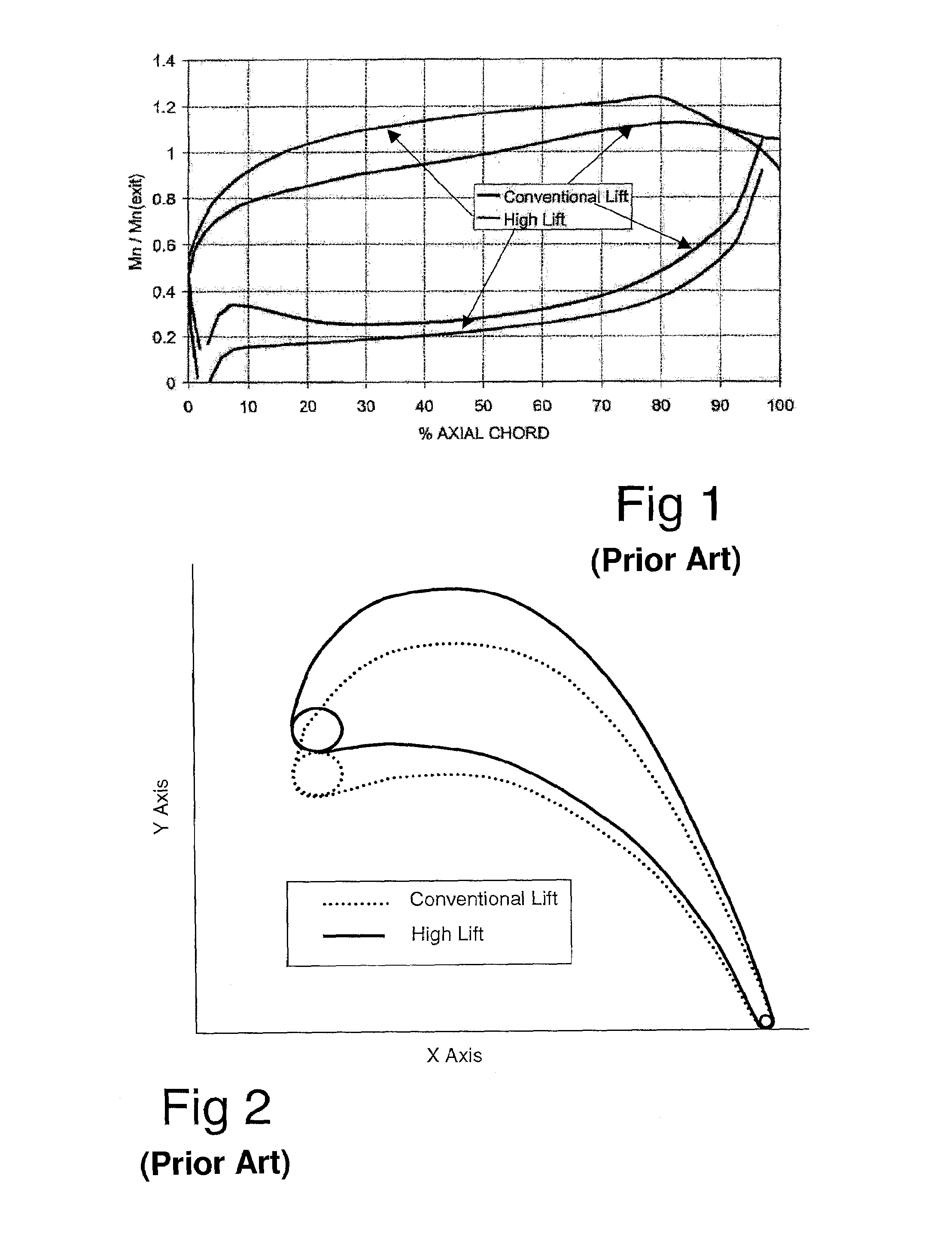
[0043]The turbine blade of the invention is of a “high lift” aerodynamic design, and FIG. 1 is a graph comparing the Mach number distributions (normalized to exit) for the mid-span aerofoil sections of two rotor blades that have the same axial chord and the same inlet and exit flow conditions as each other. The two aerofoils are differentiated as follows:

[0044]A conventional (low) lift aerofoil characterized by only a small diffusion of the flow from the Mach number point on the late suction surface to the trailing edge (known as “back surface diffusion”).

[0045]A high lift a...


PUM


Abstract

A rotor blade for a gas turbine engine includes a blade root (3) and an aerofoil projecting therefrom, the aerofoil having a leading edge and a trailing edge (5), a generally concave pressure surface (2) and a generally convex suction surface (1). The aerofoil shape of the blade varies in section along the length thereof such that:the chord-wise convex curvature of the rear suction surface decreases towards the tip (4) of the blade;the convex curvature of the early to mid suction surface increases towards the tip;the stagger of the aerofoil section increases towards the tip; andthe trailing edge (5) is a straight line.

Description

[0001]This application claims priority under 35 U.S.C. § 119 to British application number 0324203.9, filed 15 Oct. 2003, the entirety of which is incorporated by reference herein.BACKGROUND OF THE INVENTION[0002]1. Field of the Invention[0003]This invention relates to a turbine rotor blade for a gas turbine engine, to a turbine rotor incorporating such blades, and to a gas turbine engine comprising such a rotor.[0004]2. Brief Description of the Related Art[0005]The turbine of a gas turbine engine depends for its operation on the transfer of energy between the combustion gases and turbine. The losses which prevent the turbine being totally efficient are due in part to leakage flow of working fluid over the turbine blade rotor tips.[0006]In turbines with unshrouded rotor blades, a portion of the working fluid flowing through the turbine tends to migrate from the pressure surface to the suction surface of the blade aerofoil through the gap between its tip and the stationary shroud or ...

Claims


Application Information

Patent Timeline
Patent Type & Authority Patents(United States)
IPC IPC(8): F03B3/12F01D5/14
CPCF01D5/141F05B2240/31Y02T50/671Y02T50/673F05D2250/20Y10S416/05Y02T50/60
Inventor HARVEY, NEIL WILIAM
Owner ANSALDO ENERGIA SWITZERLAND AG
Why Eureka
Try Eureka