Portable optical fiber polisher

a polisher and optical fiber technology, applied in the field of polishers, can solve the problems of inefficiency of the orbital pattern of the polisher, wear of the polishing surface of the orbital polisher, and the need to replace the polishing disk, so as to simplify the polishing process and reduce the time. , the effect of less steps

Inactive Publication Date: 2007-05-15
MF LIGHTWAVE
View PDF11 Cites 15 Cited by
  • Summary
  • Abstract
  • Description
  • Claims
  • Application Information

AI Technical Summary

Benefits of technology

[0013]Another advantage is that a polisher is capable of polishing an optical fiber connector end in less steps and in substantially less time. When polishing optical fiber connector ends to meet industry standards for end face geometry, a polisher according to one embodiment of the invention is capable of using only two steps that take an aggregate amount of time of only about one minute, compared to many more steps and nearly five minutes, in aggregate, for state of the art devices. In one method using such a polisher, a first step takes about 45 seconds and combine the steps of epoxy removal, rough polishing, and radius forming. A second step, taking about 15 seconds, completes final polishing and finishing steps capable of meeting industry standards for end faces.
[0014]Another advantage is polishing without adjusting the amount of pressure needed for separate steps of the polishing process. For example, in the previous method, a fiber holding assembly of the polisher may be set up for the first step to apply a certain amount of pressure between the connector end and the polishing surface. The amount of pressure to be applied for the second step may be kept the same and does not have to vary from the first step. This capability simplifies the polishing process.
[0015]An optical fiber polisher may have an additional advantage of being portable. The polisher is capable of being light, being picked up by hand and being easily transported. It is also capable of operating on a DC power source, such as a battery.

Problems solved by technology

Orbital polishers are known to create wear of the polishing surface along circular paths.
Thus, polishing disks must often be replaced due to wear or build-up of foreign particles locally in a high-wear area on the disk.
Also, the orbital pattern of such polishers is not as efficient as the pattern that may be applied by a highly skilled human polishing a fiber end by hand.
Also, series of polishing media and pressures are used to achieve polished fiber ends that meet industry standards, but this process either requires multiple polishing disks or time consuming replacement of polishing surfaces between one polishing medium and the next in the series.
These shortcomings increase costs and reduce portability of polishing stations.
For example, polishing may require epoxy removal (30 seconds), radius forming (90 seconds), rough polishing (60 seconds), final polishing (60 seconds), and finishing polishing (60 seconds), this is an inefficient and impractical process when applied in the field and outside of a controlled plant environment.
Optical fiber polishers using the current optical fiber polishing technology have the additional problem of having to apply varying amounts of pressure between the connector end and the polishing surface for each of the five polishing steps.
These pressures are complex to set up and to maintain throughout the polishing process.
Applying too much or too little pressure during a polishing step may adversely affect the quality of the polished connector end surface.
For example, U.S. Pat. No. 6,077,154 discloses an optical fiber polishing apparatus that reduces burdens on operators for adjusting polishing pressure between steps of polishing, but fails to eliminate the need for adjusting polishing pressure between polishing steps.
If such a polisher were portable and capable of long use on a single charge of a battery, then it would be more readily adapted for use in the field than systems requiring mounting in a van and comparatively high power consumption.

Method used


Image

  • Portable optical fiber polisher
  • Portable optical fiber polisher
  • Portable optical fiber polisher

Examples


Embodiment Construction

[0024]Some examples of the invention will now be described using the drawings. While the examples are necessary to meet the written description, best mode and enablement requirements of the laws and rules for patent applications, these examples should not be considered as limiting the claims. Instead, the claims should be limited only by the language of the claims, themselves, as issued, as they would be interpreted by a person familiar with the field.

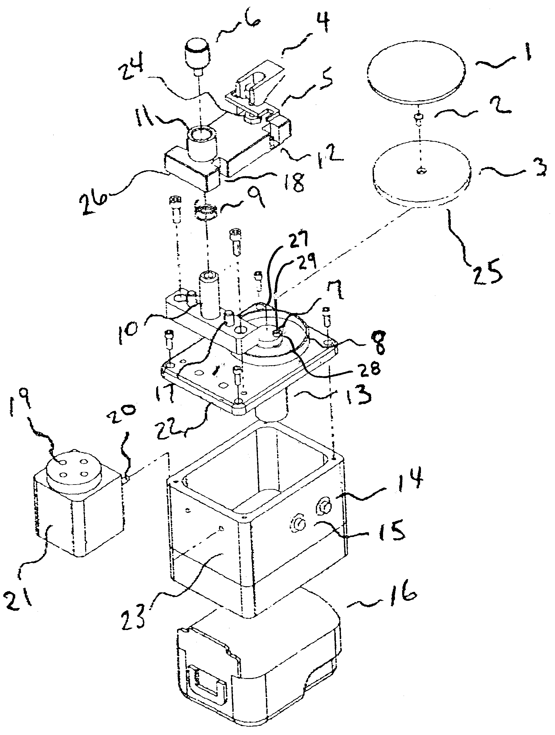
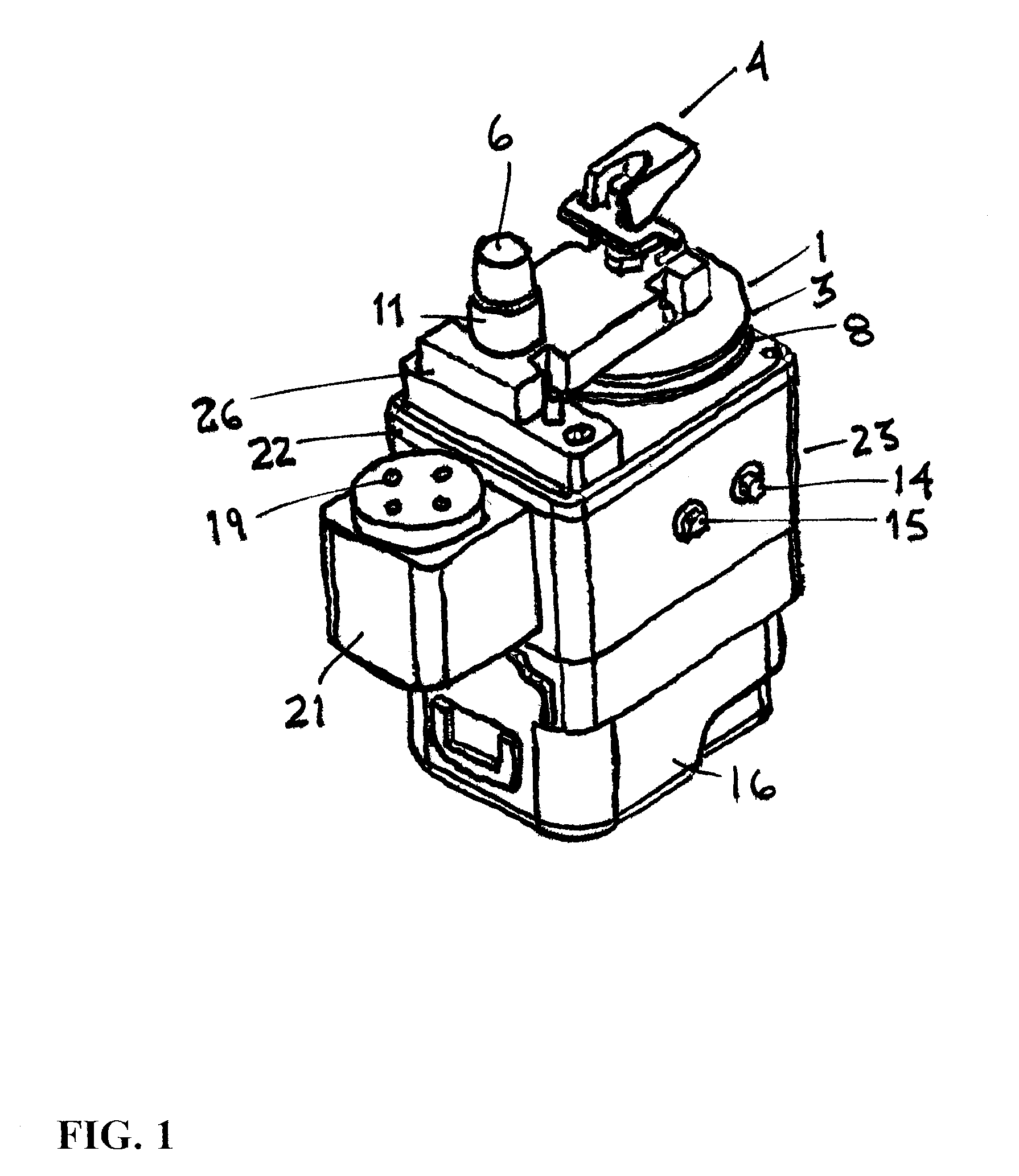
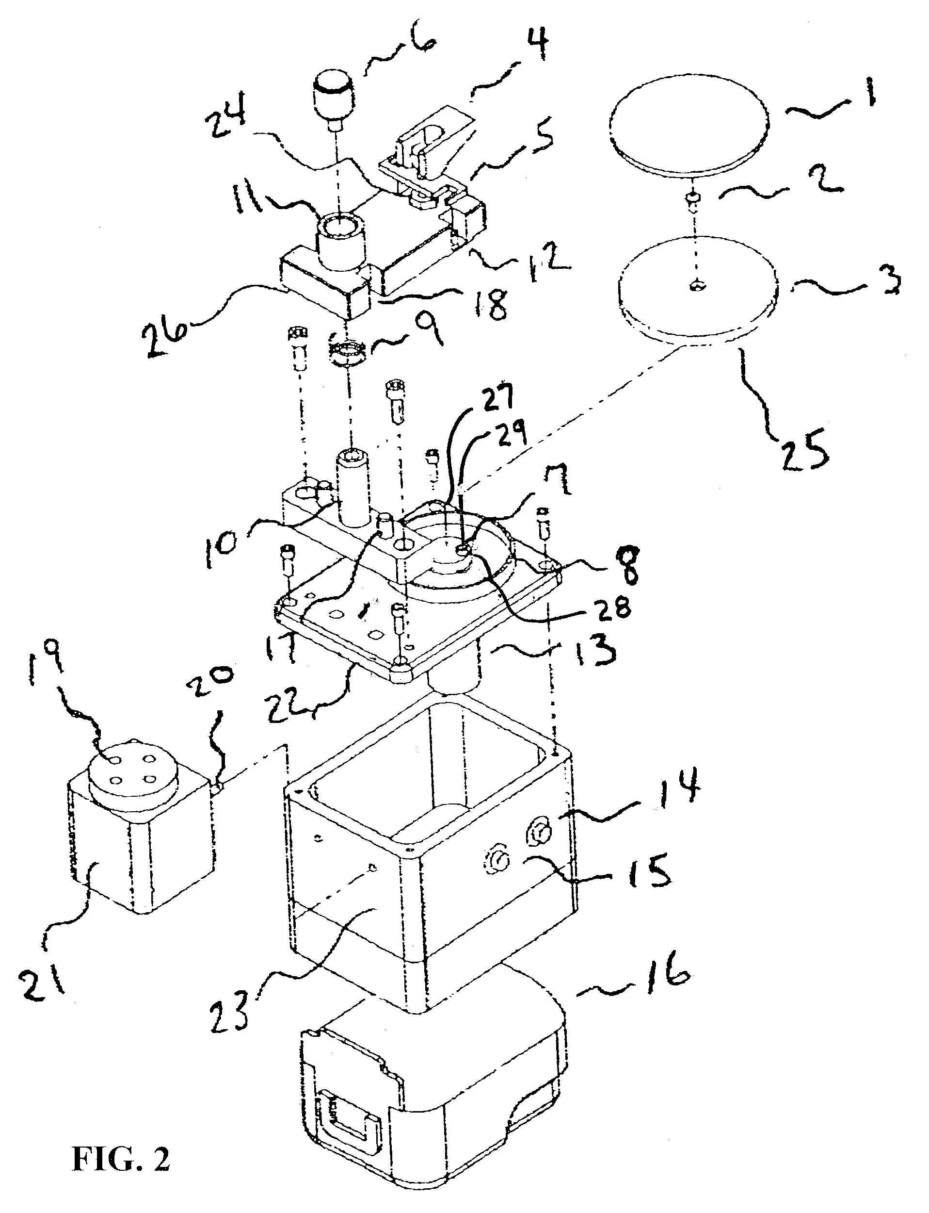
[0025]Now referring to FIGS. 1 to 3, a holding assembly 26 is mounted to the base of the polisher 23, which is capable of holding an optical fiber end using holder 4. The holding assembly 26 is capable of adjusting pressure between the fiber end and a polishing surface 1. A connector may be inserted into the connector ferrule holder 12 of the holding assembly 26 for polishing. A biasing mechanism, such as a spring 9, may be used to prevent contact between the fiber end and the polishing surface 1, until button 6 is pressed. The pressur...


PUM

PropertyMeasurementUnit
pressureaaaaaaaaaa
distanceaaaaaaaaaa
rate of rotationaaaaaaaaaa

Abstract

A polisher has an offset axis and a friction cam useful in a method of polishing that comprises a more random, elongated polishing pattern than known orbital polishers and is capable of portable use using a 9 volt battery. The method is capable of using lower contact pressures between fiber ends and a polishing surface and higher rates of rotation of the drive mechanism, reducing the polishing time for preparing fiber ends for applications. The polishing pattern changes when pressure is applied between a fiber end and the polishing surface. The fiber end provides one intermittent axis of rotation and the friction cam provides another intermittent axis of rotation.

Description

FIELD OF THE INVENTION[0001]The field relates to a polisher for polishing an optical fiber connector end.BACKGROUND[0002]Today's high speed optical network systems use optical fiber connectors to connect optical fiber ends together. These connectors have highly polished endfaces that are required to meet certain industry standards for performance and intermateability. One standard, Telcordia GR326-CORE issue 3, states that optical fiber connectors must meet defined specifications for the following three parameters of endface geometry: radius of curvature, fiber undercut, and apex offset. Consistent endface geometry creates an optimal core-to-core alignment during the mating process of two connectors.[0003]Orbital polishers are known that repeat a spiral pattern around a central drive axis, such as the pattern shown in FIG. 4. FIG. 4 shows orbital rotation about a rotational axis A of the polishing disk, which is also referred to herein as a polishing wheel, plate and / or platen, toge...

Claims


Application Information

Patent Timeline
Patent Type & Authority Patents(United States)
IPC IPC(8): B24B7/22
CPCB24B19/226
Inventor MEDEIROS, ANTHONY
Owner MF LIGHTWAVE
Why Eureka
Try Eureka