Embolic protection devices

a technology of embolic protection and filter device, which is applied in the field of filter device and system, can solve the problems of emboli not being fully vaporized and thus entering the bloodstream, affecting the patient's health, and releasing emboli into the circulatory system can be extremely dangerous and sometimes fatal to the patient, so as to prevent accidental leakage of embolic debris

Inactive Publication Date: 2007-05-15
ABBOTT CARDIOVASCULAR
View PDF763 Cites 68 Cited by
  • Summary
  • Abstract
  • Description
  • Claims
  • Application Information

AI Technical Summary

Benefits of technology

[0022]As with all of the filter elements made in accordance with the present invention, the material which can be utilized includes a variety of materials such as polymeric material which is foldable and recovers elastically to aid in the capture of the emboli trapped in the filter. Other suitable materials include braided or woven bio-compatible material which can significantly filter the desired size of the embolic debris to be captured by the filter. The filter can be formed by blowing a suitable material into the proposed shape and then cutting off unwanted portions. The perfusion openings can be drilled into the material using a laser, such as an excimer laser, or by mechanically drilling and punching the openings to the desired size and shape. Laser drilling of the holes provides accuracy, quickness and the ability to drill complex hole shapes, circles, ovals and slots. Alternatively, the central filter can be made from the same or different material from the proximal cone portion and can be welded or bonded to create an integral unit.
[0023]In one particular filter made in accordance with the present invention, the proximal cone includes advantageous features which help prevent the filter from slipping off the expandable strut assembly. These features also help to prevent trapped embolic debris from being squeezed out of the filter as the filter is bein

Problems solved by technology

However, there is one common problem which can become associated with all of these non-surgical procedures, namely, the potential release of embolic debris into the bloodstream that can occlude distal vasculature and cause significant health problems to the patient.
Additionally, while complete vaporization of plaque is the intended goal during a laser angioplasty procedure, quite often particles are not fully vaporized and thus enter the bloodstream.
When any of the above-described procedures are performed in the carotid or arteries, the release of emboli into the circulatory system can be extremely dangerous and sometimes fatal to the patient.
Debris that is carried by the bloodstream to distal vessels of the brain can cause these cerebral vessels to occlude, resulting in a stroke, and in some cases, death.
Therefore, although cerebral percutaneous transluminal angioplasty has been performed in the past, the number of procedures performed has been limited due to the justifiable fear of causing an embolic stroke should embolic debris enter the bloodstream and block vital downstream blood passages.
However, it is often difficult to control the size of the fragments which are formed, and the potential risk of vessel occlusion still exists, making such a procedure in the carotid arteries a high-risk proposition.
However, as mentioned above, there have been complications with such systems since the vacuum catheter may not always remove all of the embolic material from the bloodstream, and a powerful suction could cause problems to the patient's vasculature.
Other techniques which have had some limited success include the placement of a filter or trap downstream from the treatment site to capture embolic debris before it reaches the smaller blood vessels downstream.
However, there have been problems associated with filtering systems, particularly d

Method used


Image

  • Embolic protection devices
  • Embolic protection devices
  • Embolic protection devices

Examples


Embodiment Construction

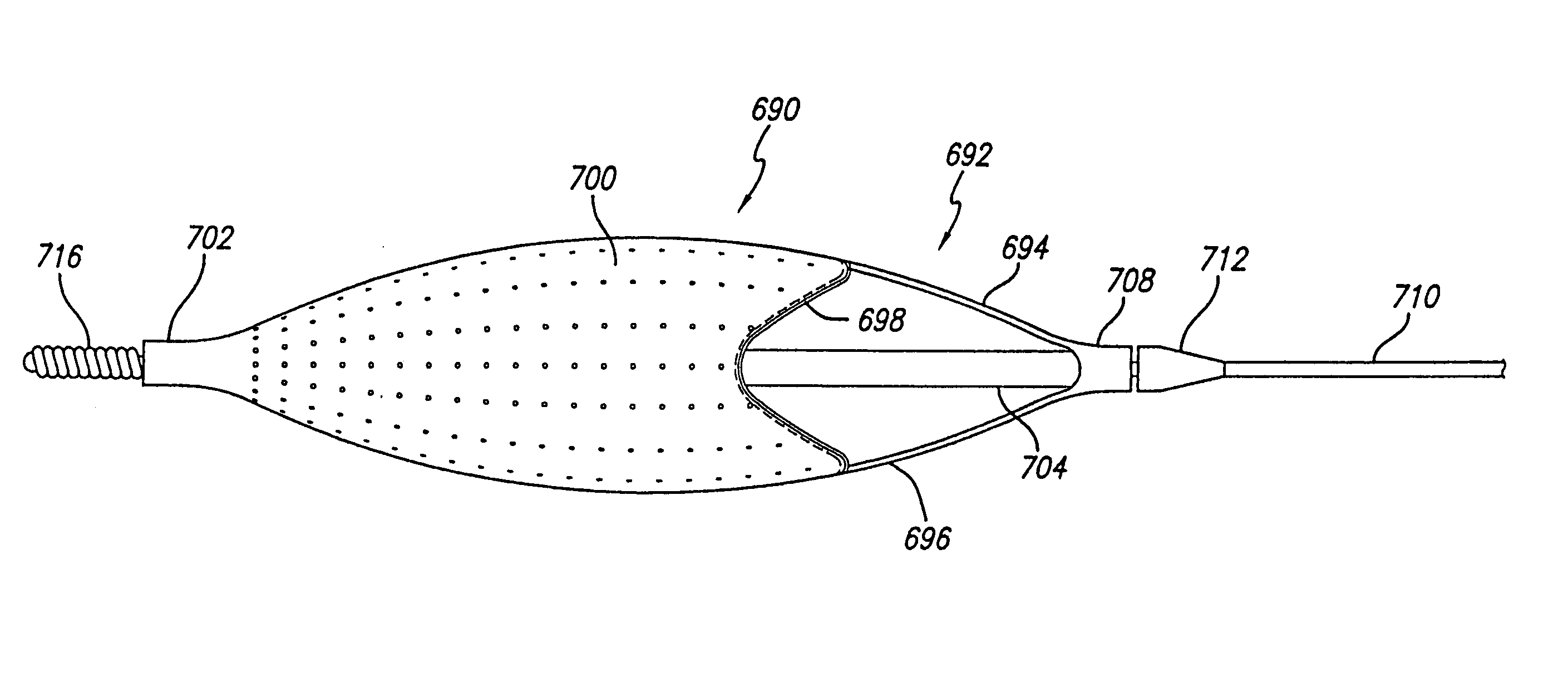
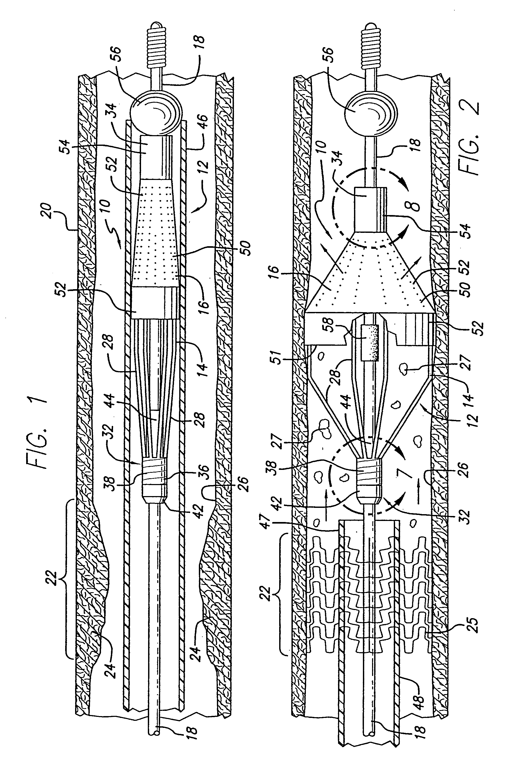
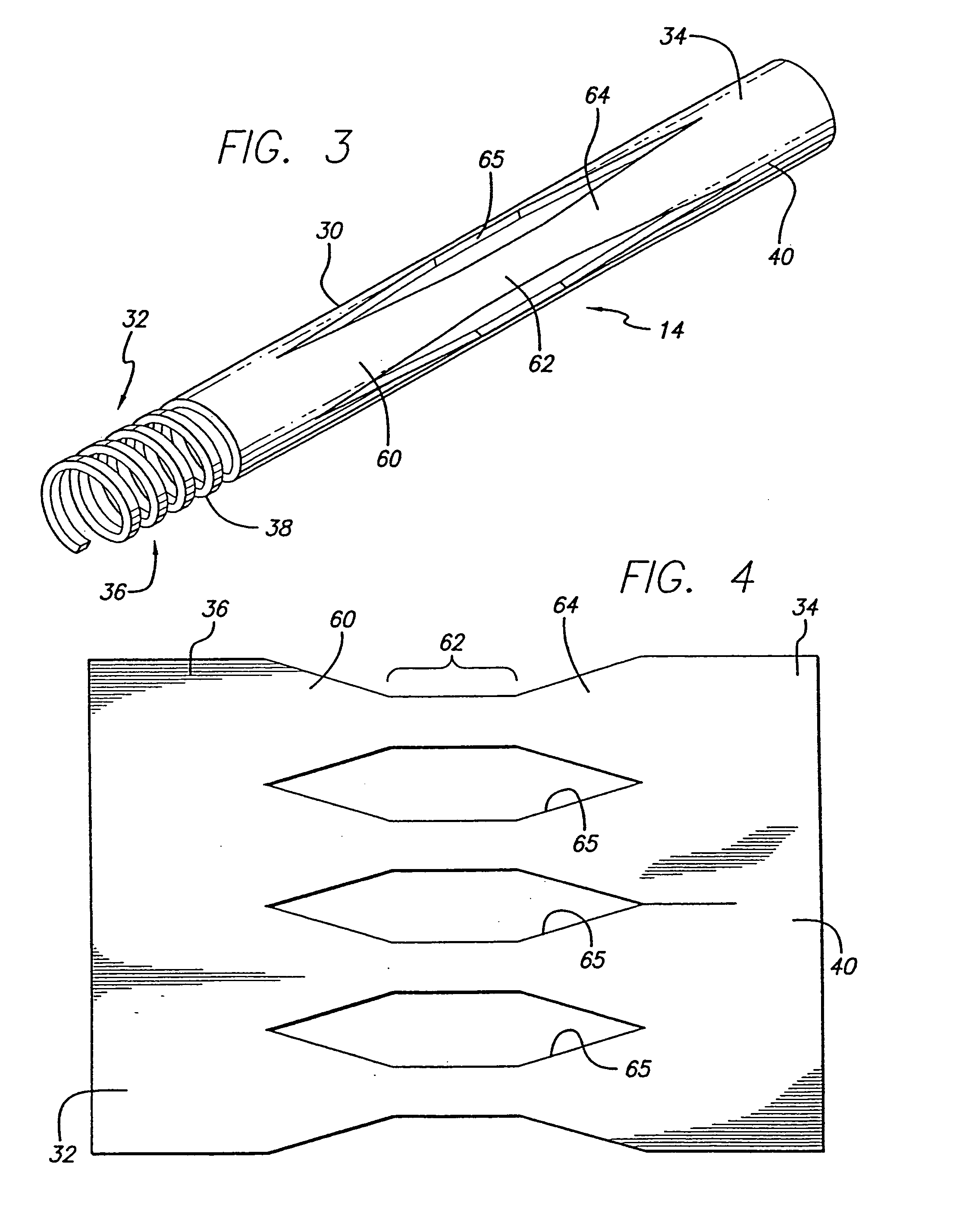
[0076]Turning now to the drawings, in which like reference numerals represent like or corresponding elements in the drawings, FIGS. 1 and 2 illustrate an embolic protection device 10 incorporating features of the present invention. In the particular embodiment shown in FIGS. 1 and 2, the embolic protection device 10 comprises a filter assembly 12 which includes an expandable strut assembly 14 and a filter element 16. The filter assembly 12 is rotatably mounted on the distal end of an elongated tubular shaft, such as a guide wire 18. Additional details regarding particular structure and shape of the various elements making up the filter assembly 12 are provided below.

[0077]The embolic protection device 10 is shown as it is placed within an artery 20 or other blood vessel of the patient. This portion of the artery 20 has an area of treatment 22 in which atherosclerotic plaque 24 has built up against the inside wall 26 of the artery 20. The filter assembly 12 is placed distal to, and d...


PUM


Abstract

An embolic protection device for use in a blood vessel when an interventional procedure is being performed in a stenosed or occluded region to capture any embolic material which may be created and released into the bloodstream during the procedure. The device includes a filtering assembly having a self-expanding strut assembly and a filter element attached thereto. In one embodiment, the filtering assembly is attached to the distal end of a guide wire and is deployed within the patient's vasculature as the guide wire is manipulated into the area of treatment. A restraining sheath placed over the filtering assembly in a coaxial arrangement maintains the filtering assembly in its collapsed position until it is ready to be deployed by the physician. Thereafter, the sheath can be retracted to expose the filtering assembly which will then self-expand within the patient's vasculature. Interventional devices can be delivered over the guide wire and any embolic debris created during the interventional procedure and released into the blood stream will enter the filtering assembly and be captured therein. Other embodiments include filtering assemblies attached to an outer tubular member and inner shaft member which apply axial force to the distal ends of the assembly to either expand or contract the struts as needed.

Description

[0001]This application is a divisional of application Ser. No. 09 / 490,319 filed Jan. 24, 2000 now U.S. Pat. No. 6,540,722 which is a continuation-in-part of application Ser. No. 09 / 476,159 filed Dec. 30, 1999 now U.S. Pat. No. 6,695,813, which is assigned to the same Assignee as the present application.BACKGROUND OF THE INVENTION[0002]The present invention relates generally to filtering devices and systems which can be used when an interventional procedure is being performed in a stenosed or occluded region of a blood vessel to capture embolic material that may be created and released into the bloodstream during the procedure. The embolic filtering devices and systems of the present invention are particularly useful when performing balloon angioplasty, stenting procedures, laser angioplasty or atherectomy in critical vessels, particularly in vessels such as the carotid arteries, where the release of embolic debris into the bloodstream can occlude the flow of oxygenated blood to the ...

Claims


Application Information

Patent Timeline
IPC IPC(8): A61M29/00A61B17/00A61F2/01A61L29/00A61M25/00A61M25/01
CPCA61F2/013A61F2002/011A61F2002/015A61F2002/018A61F2230/0006A61F2230/0067A61F2230/008A61F2/011
Inventor BOYLE, WILLIAM J.DENISON, ANDY E.HUTER, BENJAMIN C.HUTER, SCOTT J.STACK, RICHARD S.STALKER, KENT C. B.TARAPATA, CHRISTOPHERWHITFIELD, JOHN D.
Owner ABBOTT CARDIOVASCULAR
Why Eureka
Try Eureka