Burst-mode optical receiver of differential output structure

a technology of optical receiver and differential output structure, applied in the direction of dc level restoring means or bias distort correction, baseband system details, instruments, etc., can solve the problems of pulse width distortion, packets received at the receiving end are not uniform in size, and costly to replace them with fiber-based lines, etc., to improve reception sensitivity, reduce pulse width distortion, simple, reliable and inexpensive

Inactive Publication Date: 2007-05-15
SAMSUNG ELECTRONICS CO LTD
View PDF9 Cites 18 Cited by
  • Summary
  • Abstract
  • Description
  • Claims
  • Application Information

AI Technical Summary

Benefits of technology

[0016]Accordingly, the present invention has been made to solve the above-mentioned problems occurring in the prior art and provides additional advantages, by providing a burst-mode optical receiver having a differential output structure capable of significantly reducing the pulse-width distortion while improving the reception sensitivity.
[0017]One aspect of the present invention provides an additional circuit for precisely adjusting the offsets caused by a peak detector, so that a reset signal is generated automatically and a reference-voltage signal is set exactly to a middle level.
[0018]Still another aspect is that the present invention may be realized in a simple, reliable, and inexpensive implementation.
[0019]Another aspect of the present invention provides a burst-mode optical receiver having a differential output structure and includes: a trans-impedance amplifier for converting currents indicating burst-mode signals into voltage signals; a bottom level detector for detecting the bottom level of signals outputted from the trans-impedance amplifier; an automatic gain controller for automatically adjusting a gain to prevent the output waveforms of the trans-impedance amplifier from being distorted after receiving the bottom-level signals detected by the bottom-level detector; a top-level detector for detecting the top level of signals outputted from the trans-impedance amplifier, a pair of resistors for generating a signal-reference voltage from the bottom- and top-level voltages, one side of each resistor being connected to the bottom- and top-level detectors, respectively, and the other sides of each resistor being connected to each other; and, a differential buffer for receiving outputs from the trans-impedance amplifier and the signal reference voltage from the pair of resistors and for eliminating the offsets generated from the bottom- and top-level detectors in order to supply two differential outputs.

Problems solved by technology

As such, it would be very costly to replace them with the fiber-based lines.
Each subscriber transmits data at the respective assigned time, but the packets received at the receiving ends are not uniform in size due to the path differences between the OLT and each subscriber.
Accordingly, there is a problem in that the reference signal generated from the peak detector 20 is not matched with the mean level of the output-data signal, thus still generates a pulse-width distortion and degrades the sensitivity of the optical detector.

Method used


Image

  • Burst-mode optical receiver of differential output structure
  • Burst-mode optical receiver of differential output structure
  • Burst-mode optical receiver of differential output structure

Examples


Embodiment Construction

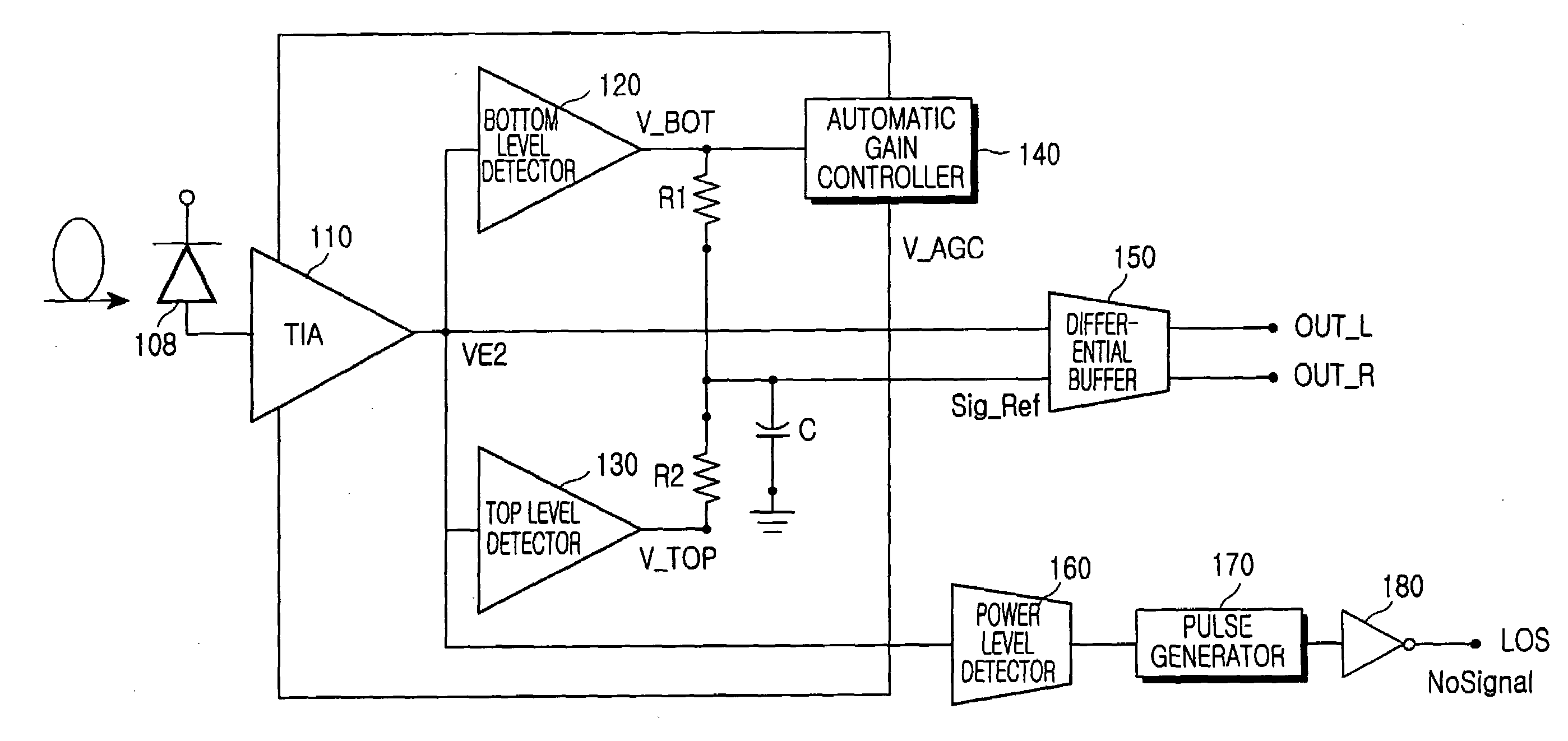
[0030]FIG. 4 is a circuit diagram of a burst-mode differential preamplifier of a differential-output structure according to the teachings of the present invention. As shown, the burst-mode differential preamplifier includes an optical detector 108 for converting an in-put-burst optical signal into a current signal according to the signal intensity of the input-burst optical signal. The output of the optical detector 108 is connected to a trans-impedance amplifier (TIA) 110. The TIA 110 amplifies the current received from the optical detector 108 and supplies the amplified output signal VE2 to a bottom-level detector 120 and a top-level detector 130.

[0031]The bottom-level detector 120 detects a bottom level of the signal output from the TIA 110, and the top-level detector 130 detects a top level of the signal output from the TIA 110. The bottom voltage level detected from the bottom-level detector 120 is supplied to an automatic gain controller (AGC) 140 and, in response, the AGC 140...


PUM


Abstract

A burst-mode optical receiver of a differential-output structure is disclosed. The burst-mode optical receiver includes a trans-impedance amplifier for converting currents indicating the burst-mode signals into voltage signals, a bottom-level detector for detecting the bottom level of signals outputted from the trans-impedance amplifier, an automatic gain controller for automatically adjusting a gain to prevent the output waveforms of the tran-simpedance amplifier from being distorted after receiving the bottom-level signals detected by the bottom-level detector, a top-level detector for detecting the top level of signals outputted from the trans-impedance amplifier, a pair of resistors for generating a signal-reference voltage from the bottom- and top-level voltages, one side of each resistor being connected to the bottom- and top-level detectors, respectively, and the other sides of each resistor being connected to each other, and a differential buffer for receiving outputs from the trans-impedance amplifier and the signal-reference voltage from the pair of resistors and for eliminating the offsets generated from the bottom- and top-level detectors in order to supply two differential outputs.

Description

CLAIM OF PRIORITY[0001]This application claims priority to an application entitled “BURST-MODE OPTICAL RECEIVER OF DIFFERENTIAL OUTPUT STRUCTURE,” filed in the Korean Intellectual Property Office on Apr. 15, 2002 and assigned Ser. No. 2002-20489, the contents of which are hereby incorporated by reference.BACKGROUND OF THE INVENTION[0002]1. Field of the Invention[0003]The present invention relates to a burst-mode optical receiver and, more particularly, to a burst-mode optical receiver for enhancing an available bit rate in a passive network.[0004]2. Description of the Related Art[0005]For the future generation of communications, optical subscriber networks, such as FTTH (Fiber to the Home), will be required to install optical fiber lines directly to the homes of subscribers for the transmissions / reception of information at a higher speed. The subscriber networks have been traditionally constructed with copper-based lines. As such, it would be very costly to replace them with the fib...

Claims


Application Information

Patent Timeline
Patent Type & Authority Patents(United States)
IPC IPC(8): H04B10/06H03F3/45H03F1/08H03F3/08H03G3/20H03G3/30H04B10/272H04B10/40H04B10/50H04B10/516H04B10/524H04B10/54H04B10/556H04B10/58H04B10/60H04B10/61H04B10/69H04L25/06
CPCH04L25/062H04B10/60H04B10/69
Inventor DOH, HEE-CHANKI, HYEON-CHEOLOH, YUN-JEPARK, GIL-YONGPARK, TAE-SUNGWON, SHIN-HEE
Owner SAMSUNG ELECTRONICS CO LTD
Why Eureka
Try Eureka